Cooling Loop Installation 4-11
PowerFlex® 700L Liquid-Cooled Drive User Manual
Publication 20L-UM001D-EN-P
Frame 3A or 3B Complete Drive
For locations of the coolant inlet and outlet connections on PowerFlex 700L
Liquid-Cooled Frame 3A Complete Drives, refer to Figure 3.18
(front and
side views). For locations on Frame 3B Complete Drives, see Figure 3.21
(front and side views).
The rated working pressure of the Frame 3A and 3B Complete Drive is 6.89
bar (100 PSI). Coolant supply and return lines should be sized for 76 LPM
(20 GPM) / 6.89 bar (100 PSI) service with a maximum operating
temperature of 40°C (105°F). The required operating flow rate is specified
in Table 4.G
.
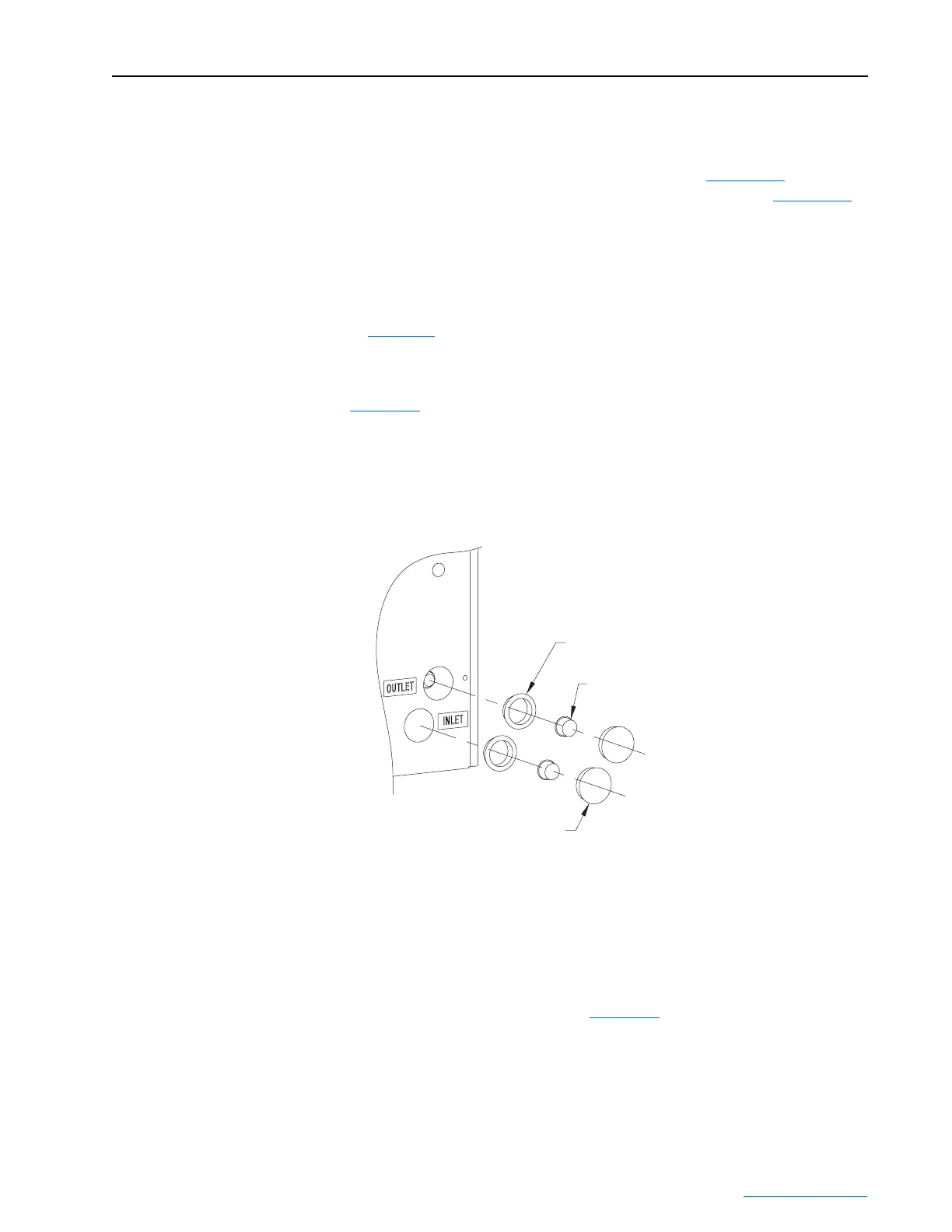
Before connecting the coolant hoses to the Complete Drive hose fittings
located at the lower-right back corner of the drive enclosure, refer to
Figure 4.8
and:
1. Remove the factory-installed hose fitting plugs and the enclosure wall
dome plugs.
2. Install the factory-supplied snap bushings to the enclosure wall.
Figure 4.8 Frame 3A and 3B Complete Drive Coolant Connection Components
Frame 3A and Frame 3B Complete Drive coolant connections are made
using 37 degree flare fittings which have a:
• 1-inch nominal size
• “-16” SAE dash size
• 1 5/16-12 UN/UNF-2B external thread size
The mating connection is shown in Figure 4.9
. The mating process includes
the following steps:
Enclosure Wall
Snap Bushings
Enclosure Wall
Dome Plugs
Hose Fitting Plugs
 Loading...


