3-12 Frame 3A and 3B Installation
PowerFlex® 700L Liquid-Cooled Drive User Manual
Publication 20L-UM001D-EN-P
Supporting the Power
Module
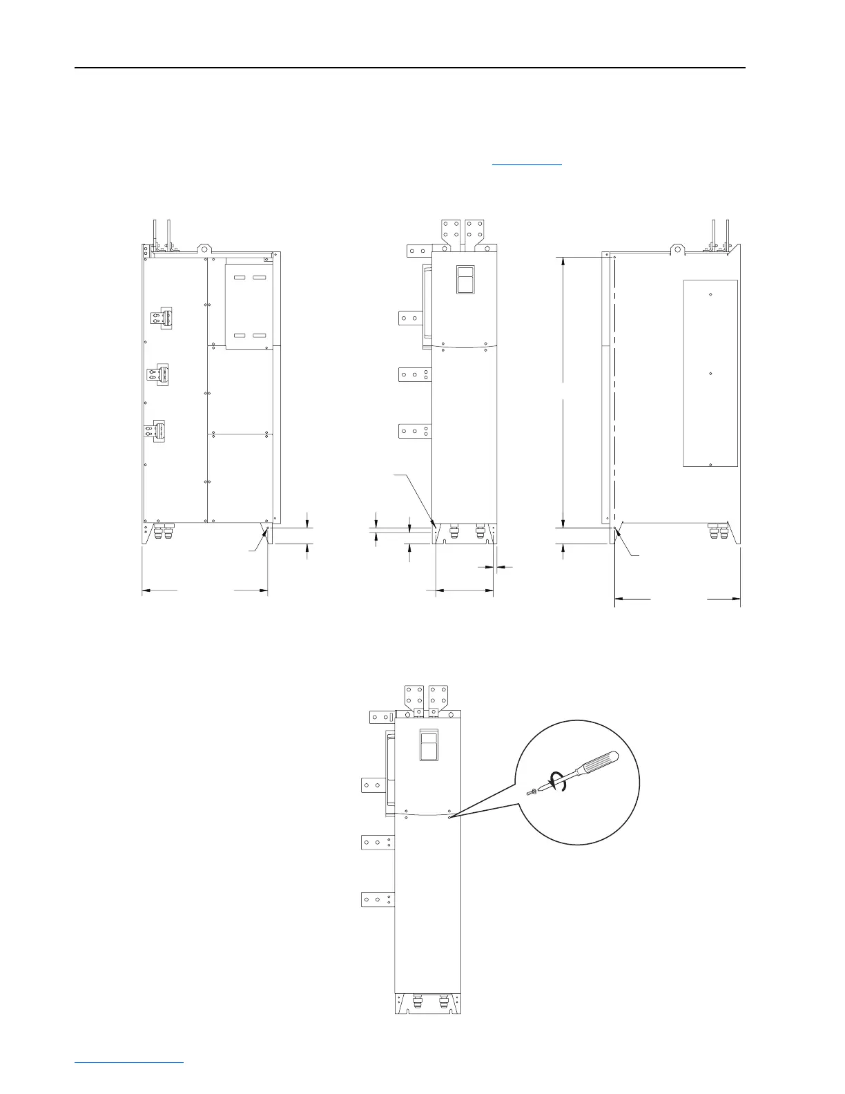
The Frame 3 power module has features for attaching support brackets with
screws. The support brackets are required to prevent mechanical damage to
the AC input, DC, and AC output bus bars. The feature locations, feature
size, and screw type are shown in Figure 3.12
.
Figure 3.12 Frame 3 Power Module Support Locations
Removing the Power Module
Covers
Dimensions are in millimeters (inches).
Ø 0.213 Thru Hole
Suitable for M6 x 1.0
Taptite Screw
4 Places
Clinch Nut
Suitable for M6 x 1.0
Machine Screw
2 Places
Clinch Nut
Suitable for M6 x 1.0
Machine Screw
515 (20.26)
66 (2.59)
19 (0.75)
15 (0.58)
47 (1.84)
66 (2.59)
236 (9.28)
515 (20.26)
1107 (43.59)
(Frame 3B Power Module shown)
LEFT SIDE VIEW FRONT VIEW RIGHT SIDE VIEW
Inverter or Converter Module
(Frame 3B Inverter Power Module shown)
(4 Captive Screws)
 Loading...


