2-12 Frame 2 Installation
PowerFlex® 700L Liquid-Cooled Drive User Manual
Publication 20L-UM001D-EN-P
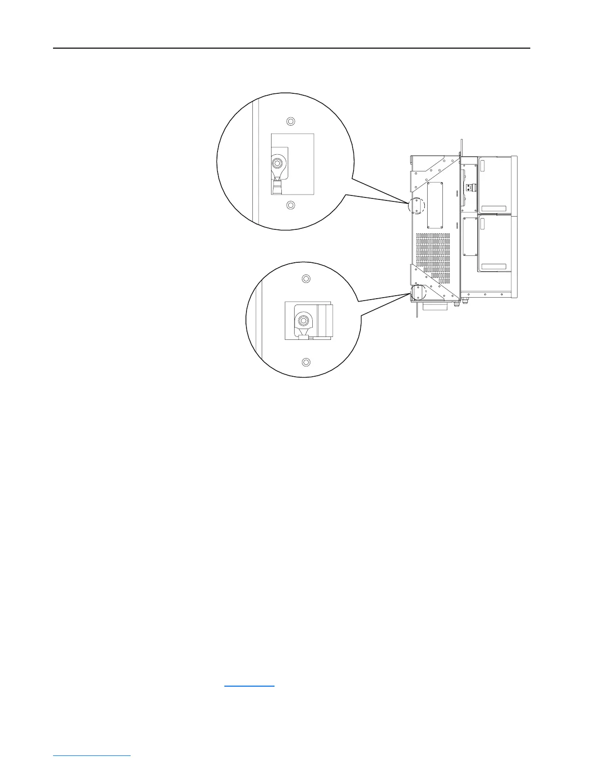
Figure 2.11 Removing Common Mode Capacitor and MOV
Power Wiring
This section describes incoming line components and how to install them,
and provides instructions on wiring input power, output contactors, motor
overload protection, and output wiring to the motor.
Installing Transformers and Reactors (Not Recommended)
Frame 2 drives may be used on distribution systems with 200,000 amps or
less symmetrical fault current capacity. The drive input components consist
of a 3% line reactor and a harmonic line filter. Additional input inductance
is not recommended.
Selecting/Verifying Control Transformer Voltage
A control transformer is used to match the input line voltage of the drive to
the 115V control voltage. If your line voltage is different than the voltage
class specified on the drive nameplate, it may be necessary to change
transformer taps as described below.
1. Unfasten seven screws and remove the bottom drive cover
(Figure 2.10
).
Side View of Drive
Common Mode
Capacitor Removal
MOV Removal
 Loading...


