2-6 Frame 2 Installation
PowerFlex® 700L Liquid-Cooled Drive User Manual
Publication 20L-UM001D-EN-P
Rotating the Drive About the Board
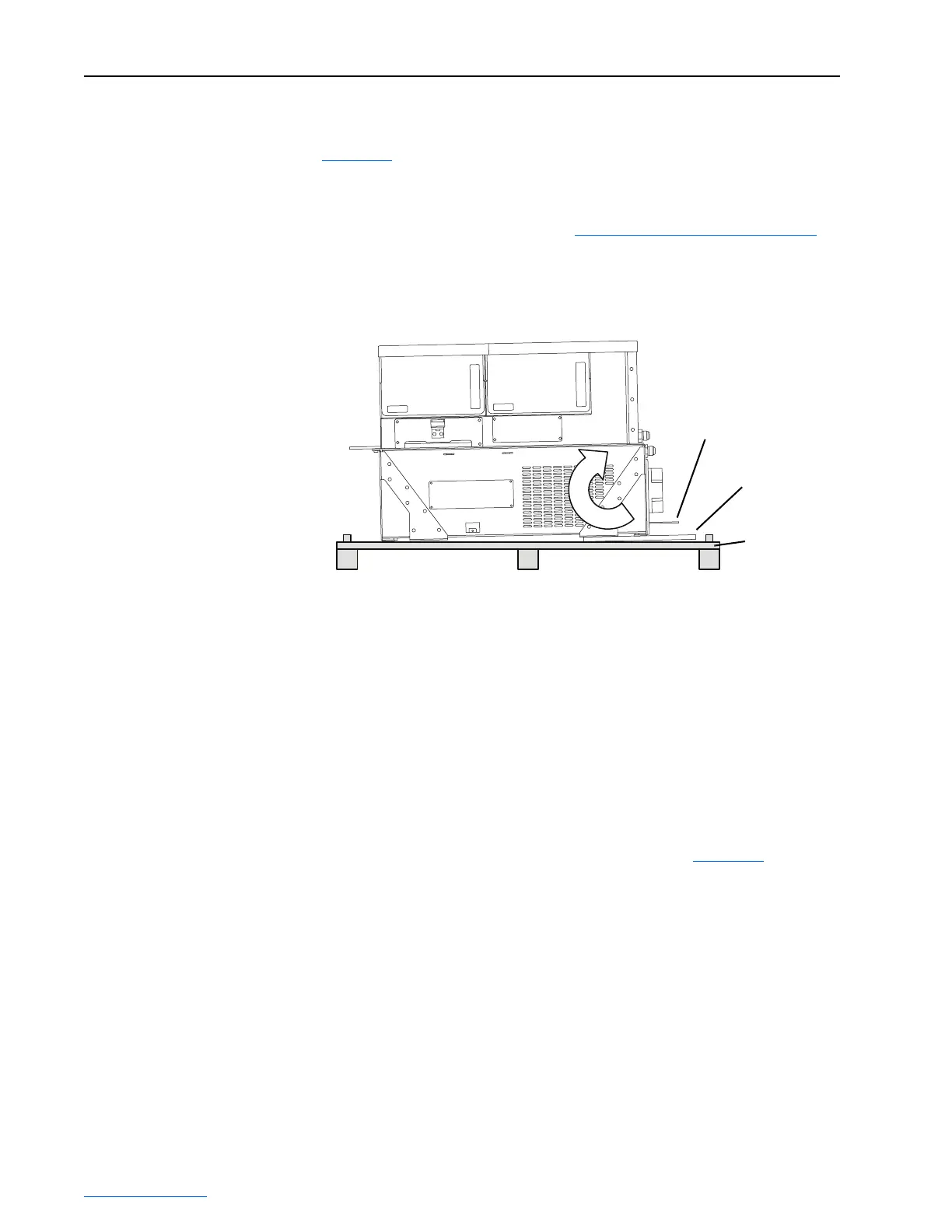
Figure 2.6 shows the drive, with the lifting feet attached, on a skid. To avoid
damage to the drive input terminals when lifting the drive to a vertical
position, do the following:
1. After the straps are in place (see Applying Strap Angles
on page 2-5),
carefully lift the drive to rotate it 90° to a vertical position.
2. Remove the lifting feet before installing the drive into the enclosure.
Figure 2.6 Frame 2 Drive on Skid
Mounting Requirements
The PowerFlex700L Frame 2 drive is a single integrated assembly
consisting of a filter section and a power section. The filter section provides
the mounting feet and represents greater than 50% of the approximate 186
kg (410 lb.) total weight.
1. The Frame 2 drive should be mounted into an enclosure that is designed
according to Electrical Equipment Pollution Degree 2 requirements.
2. Any enclosure mounting panel needs to be sized and fastened
appropriately to accommodate for the weight of the drive.
3. The Frame 2 drive is designed to use eight M8 x 1.25 fasteners in
mounting slots shown in Detail A and Detail B of Figure 2.1
.
4. The M8 x 1.25 fasteners shall be class 5.8 or greater.
5. The fasteners shall use a lock washer or similar mechanism to prevent
loosening after mounting.
6. All M8 x 1.25 fastener threads shall engage a steel panel with 6 - 7 full
threads or a permanent backing nut such as a weld nut or a
self-clinching PEM
®(1)
nut with 4 full threads.
7. M8 x 1.25 fasteners shall be tightened to 11.3 ± 2.8 N•m (100 ± 25
in•lbs) unless the lock washer mechanism requires a different torque. If
this is the case, the holding force shall be equivalent.
Skid
Input Terminals
Lifting Feet
(1)
PEM is a registered trademark of PennEngineering.
 Loading...


