4-4 Cooling Loop Installation
PowerFlex® 700L Liquid-Cooled Drive User Manual
Publication 20L-UM001D-EN-P
Chiller
The chiller utilizes refrigerant to transfer heat from a liquid to air. This is a
simple closed loop system — it does not require a water supply from the
user. A chiller can achieve almost any coolant temperature required.
Coolant temperature should be at or above ambient temperature to avoid
condensation on drive components.
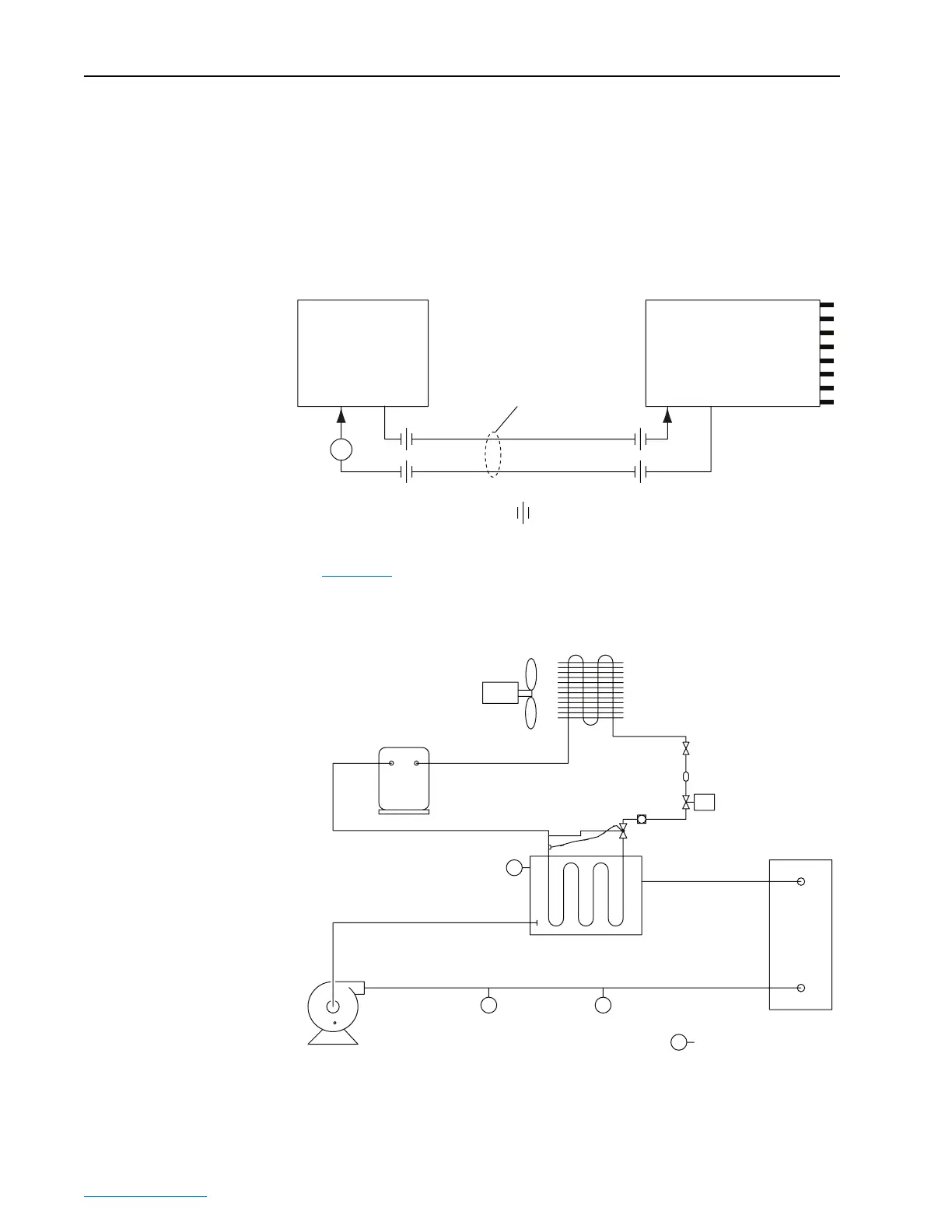
Figure 4.5 Drive and Chiller Plumbing Arrangement
Figure 4.6 shows a cooling loop diagram for a typical chiller.
Figure 4.6 Chiller Plumbing Diagram
PowerFlex 700L
Drive
Inlet
Flow
Indicator
Drive
Outlet
Hose Kit
= hose or pipe connection
To
Drive
Inlet
Radiator
From
Drive
Outlet
Chiller
Drive
Out
In
Reservoir
Pump
Condenser/Subcooler
Fan
Compressor
SOL
LS
TE FS
TE
Ambient
Sensor
Sight Glass
Thermostatic
Expansion Valve
Filter-Drier
Drive Coolant
Temperature
Flow
Switch
Level
Switch
 Loading...


