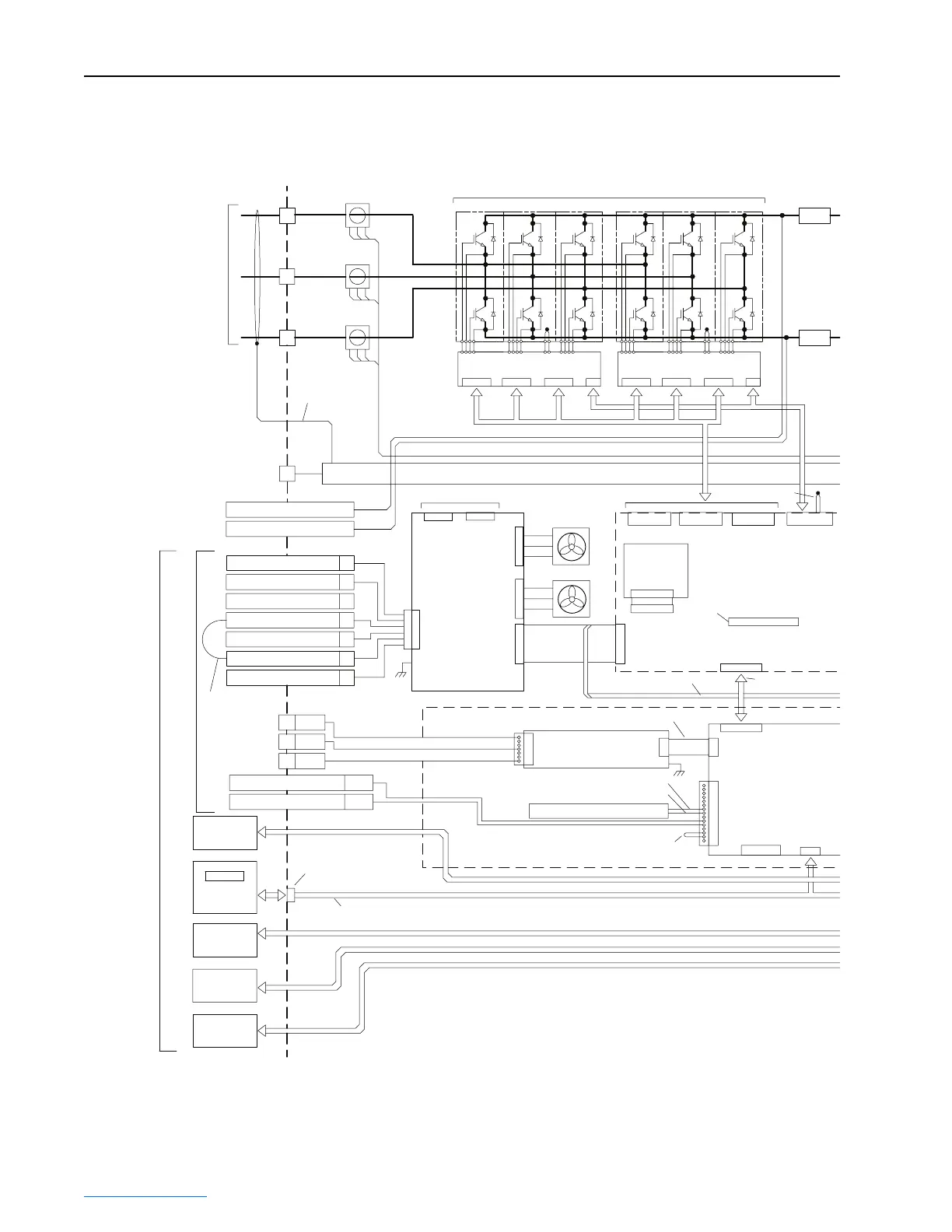
C-6 Frame 3A and 3B Schematics
PowerFlex® 700L Liquid-Cooled Drive User Manual
Publication 20L-UM001D-EN-P
Frame 3A Converter/Inverter Power Module Wiring Diagram – 400/690V, 3 Phase
External
HIM Option
I/O
and Network
Control
and Signal
I/O
and Network
Shielded Cable, Grounded Both Ends
CHASSIS
J4
J1
J6
DC (-)
DC (+)
J4
L1 Gate
J9
J11
J8
J6
L3 Gate L2 Gate
J5
J5
NTC
J1
Chillplate NTC
Control CassetteBottom
Active Converter
Control PCB Option
J1
40-Pin
Shielded Cable
J7
J2
400V/
480V
J3
600V/
690V
Flange-Mount 8-Pin
Female Mini-DIN
J8
DPI
J4
Power
and Signal
15
P1
1
Addressable Power PCB
DC Bus Input
2
4
5
6
7
J2
P2-7
L3
P2-4
P2-1
L2
L1
P1-9
P1-10
Converter
Rating Plug
PCB Option
28-Pin
Board-to-Board
J2
Three Phase
A.C. Input
Source
Power
Shield
Earth Ground
Input
Filter
User
Connections
Factory-Installed
Gate Kill Jumper
CT3
CT2
L3
L2
CT1
L1
DC (-) Testpoint
DC (+) Testpoint
PE
Gate Enable
Inductor Overtemp
Precharge Feedback
Precharge Coil
+24V
3
120 VAC Neutral
1
120 VAC Line
Shunt Trip Out
Shunt Trip Return
Power Supply
PCB Option
Fan 1
Fan 2
34-Pin Ribbon Cable
20-Pin Board-to-Board
J1
P2
7
4
1
SOC_IN+ P1-7
SOC_IN- P1-8
<<< SOC Signal - PF700 Vector
Factory-Installed Gate
Kill Jumper P1-13, 14
Voltage Feedback
Resistor PCB Option
Converter IGBT Modules Option
N
T
C
N
T
C
#1 - Bottom #2 - Lower Middle
IGBT Interface PCB IGBT Interface PCB
J1 J1J2 J3 J4 J2 J4J3
 Loading...


