Troubleshooting 6-7
PowerFlex® 700L Liquid-Cooled Drive User Manual
Publication 20L-UM001D-EN-P
Replacement of Door Filter
of the Input Filter Cabinet
(Frames 3A and 3B)
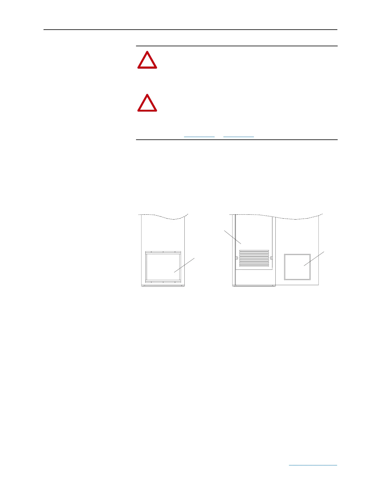
When the door filter of the Input Filter Cabinet requires replacement,
remove the dirty filter and replace it with an equivalent clean filter.
Important:If the CE Shield Barrier has been removed for servicing, it
should be reinstalled to restore the casual touch protection this
barrier provides.
Figure 6.2 Input Filter Cabinet Door Filter Replacement
!
ATTENTION: Only qualified personnel familiar with adjustable
frequency AC drives and associated machinery should plan or
implement the installation, start-up, and subsequent maintenance
of the system. Failure to comply may result in personal injury and/
or equipment damage.
!
ATTENTION: To avoid an electric shock hazard, verify that the
voltage on the bus capacitors has discharged completely before
servicing. After removing power to the drive, wait 5 minutes for
the bus capacitors to discharge. Measure the DC bus voltage at the
DC+ and DC- TESTPOINT sockets on the front of the power
module (Figure 3.14
or Figure 3.27). The voltage must be zero.
Input Filter Cabinet
(Door Closed)
Input Filter Cabinet
(Door Open)
Filter
Filter
CE Shield Barrier
 Loading...


