2-20 Frame 2 Installation
PowerFlex® 700L Liquid-Cooled Drive User Manual
Publication 20L-UM001D-EN-P
Synchronization
Connections
Coupled Power Modules
Frame 2 combined Converter/Inverter Power Modules are only configured
as coupled power modules. Coupling the Converter and Inverter is achieved
by using two factory-installed cables: a control synchronization cable and
an inverter-to-converter DPI communication cable. The two cables are
described in the next two subsections.
Control Synchronization Cable
To enable synchronization between the Inverter control printed circuit board
and the Converter control printed circuit board, a factory-installed control
synchronization cable connects each board. No user connection is required.
However, the connection method is different for PowerFlex 700L
Liquid-Cooled AC drives with 700 Vector Control and 700S Phase II
Control. The 700 Vector Control synchronization cable connection is shown
in Figure 2.17
. The 700S Phase II Control synchronization cable connection
is shown in Figure 2.18
.
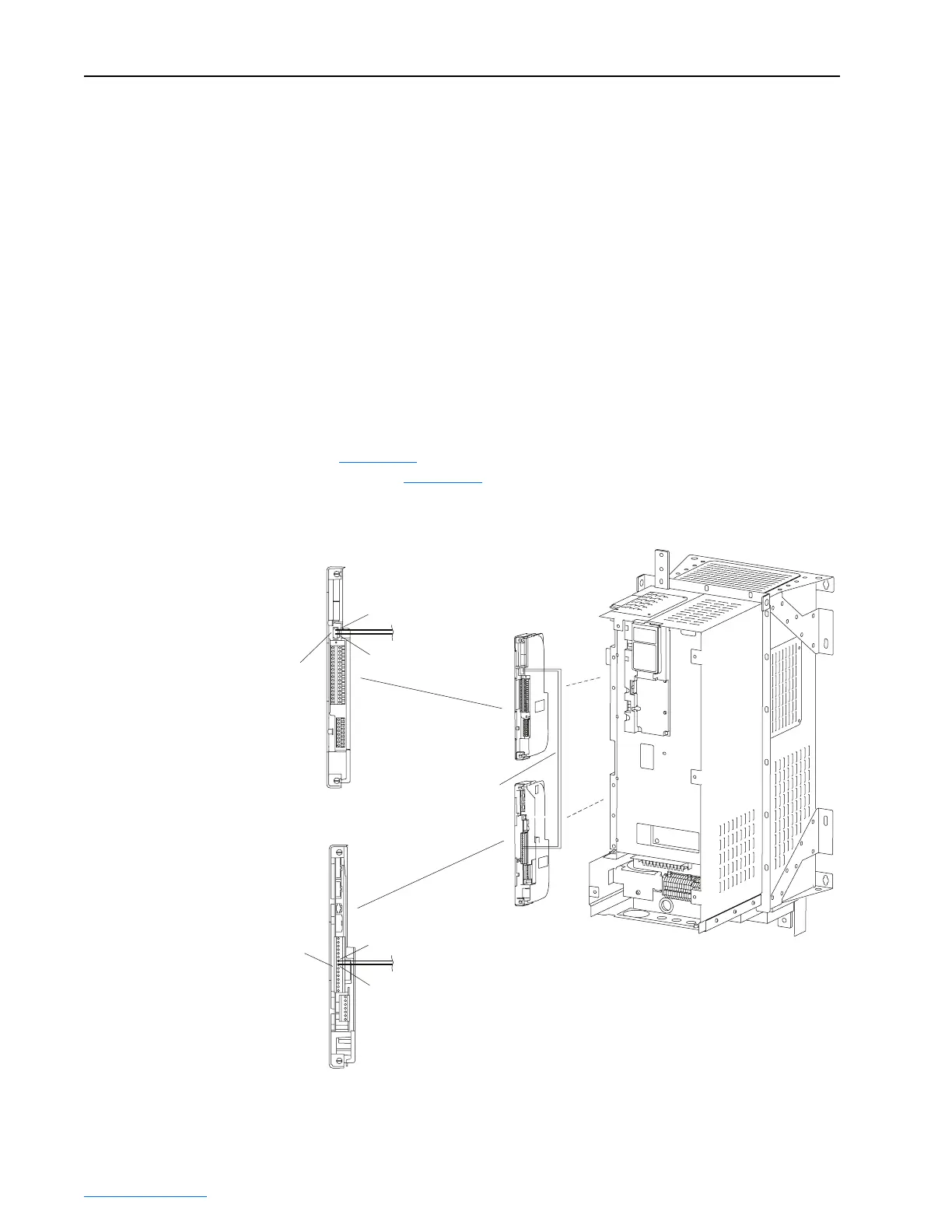
Figure 2.17 Frame 2 700 Vector Control Synchronization Cable Connection
TB2 Header on
700 Vector
Control Cassette
P1 Terminal Block
on Active Converter
Control Cassette
TB2-2
TB2-1
P1-7
1
P1-8
15
Control Synchronization
Cable (Factory-Installed)
 Loading...


