Frame 2 Installation 2-19
PowerFlex® 700L Liquid-Cooled Drive User Manual
Publication 20L-UM001D-EN-P
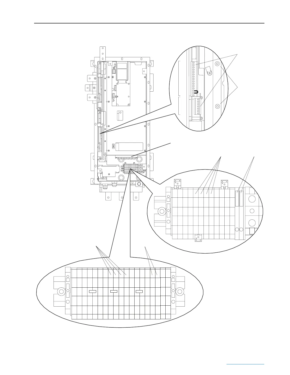
Figure 2.16 Frame 2 Drive Control Wiring Terminal Locations
P1
P2
1
15
7
1
SHLD
SHLD
➊
➋
➌
TB1
Customer Connection Side
TB1 When TB4 is Present
1b 5
PS-
PS+
1b 6
1b 7
1b 8
1b 1
1b 2
1b 3
1b 4
1b 9
1b 10
1b 11
1b 12
1a 5
1a 6
1a 7
1a 8
1a 1
1a 2
1a 3
1a 4
1a 9
1a 10
1a 11
1a 12
➍
➌
TB1
Customer Connection Side
TB1 When TB4 is Not Present
➍
1b15
1b14
1b13
1b12
1b11
1b10
1b9
1b8
1b7
1b6
1b5
1b4
1b3
1b2
1b1
PS-
PE1PE2
PE1PE2
PS+
1a15
1a14
1a13
1a12
1a11
1a10
1a9
1a8
1a7
1a6
1a5
1a4
1a3
1a2
1a1
PS-
PS+
TB4 (NOTE: On drives without TB4,
there are additional terminals on TB1.)
 Loading...


