Cooling Loop Installation 4-5
PowerFlex® 700L Liquid-Cooled Drive User Manual
Publication 20L-UM001D-EN-P
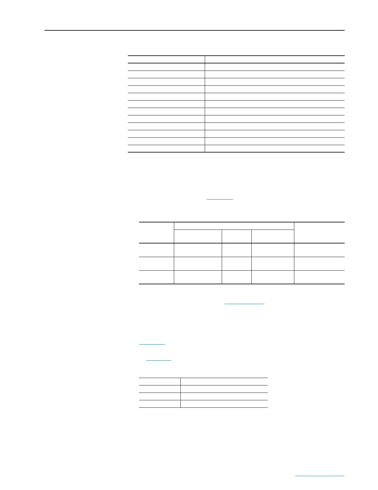
The main components of the chiller cooling loop include:
Recommended Cooling
Loops
Liquid-to-Liquid Heat Exchanger
Recommended Liquid-to-Liquid Heat Exchangers from Rockwell
Automation are listed in Table 4.A
.
Table 4.A Liquid-to-Liquid Heat Exchanger Requirements
Table 4.B lists the estimated amount of coolant needed for the drive loop
based on the drive frame size. For recommended drive loop coolants, refer
to Table 4.F
.
Part Description
Compressor Forces the refrigerant into a smaller space.
Fan Blows air across the condenser/subcooler.
Condenser/Subcooler Cools the refrigerant.
Filter-Drier Filters the refrigerant.
Sight Glass Allows viewing of the level of drive coolant in the reservoir.
Thermostatic Expansion Valve Allows for expansion of the refrigerant.
Level Switch Senses the level of coolant in the reservoir.
Reservoir Allows for expansion of coolant.
Pump and Motor Circulates drive coolant.
Drive Coolant Temperature Sensor Senses the drive coolant temperature used for the dew point control.
Drive Coolant Flow Switch Measures the drive coolant flow rate.
Ambient Sensor Senses the ambient temperature used for the dew point control.
Drive
Frame Size
Supply Loop Requirements
(1)
(1)
Supply loop requirements are for the input to the heat exchanger. These are not requirements for the drive. The
output of the heat exchanger is designed to meet the flow and pressure requirements of the drive. For the flow
and pressure requirements of the drive, see Table 4.G on page 4-8
.
Liquid-to-Liquid Heat
Exchanger Cat. No.
(3)
(3)
Recommended cooling loops shown are based on a single drive per cooling loop. Consult the factory for use of
multiple drives on one cooling loop.
Minimum Flow @
Pressure
(2)
(2)
The minimum pressure applies to the pressure drop across the heat exchanger and does not take into account
additional pressure drop in the system such as piping or hosing.
Maximum
Pressure
Temperature
Range
2 15.1 LPM @ 0.83 bar
(4 GPM @ 12 PSI)
8.62 bar
(125 PSI)
0-40°C (32-104°F) 20L-LL13K-P75A
3A 22.7 LPM @ 0.83 bar
(6 GPM @ 12 PSI)
8.62 bar
(125 PSI)
0-35°C (32-95°F) 20L-LL13K-P75A
3B
56.8 LPM @ 0.83 bar
(15 GPM @ 12 PSI)
8.62 bar
(125 PSi)
0-35°C (32-95°F) 20L-LL24K-1P0A
Table 4.B Estimated Coolant Amount for the Drive Loop
Drive Size Estimated Amount of Coolant
(1)
(1)
The estimated amount of coolant is based on the heat exchanger
using 1.2 m (4 ft.) hoses. Longer hoses require more coolant. The
maximum hose length of 9.1 m (30 ft.) would require up to an
additional 2.8 liters (3/4 gal.).
Frame 2 15.1 liters (4 gal.)
Frame 3A 19 liters (5 gal.)
Frame 3B 19 liters (5 gal.)
 Loading...


