Frame 2 Installation 2-7
PowerFlex® 700L Liquid-Cooled Drive User Manual
Publication 20L-UM001D-EN-P
Verifying the Drive’s Watts
Loss Rating
When mounting the drive inside of an enclosure, you should determine the
watts loss rating of the drive from Table A.E on page A-6
. This table lists
the typical full load power loss watts value at 4 kHz (rated carrier
frequency). Ensure that the enclosure is adequately ventilated with 0-50°C
(32-122°F) ambient air based on the drive’s watts loss rating.
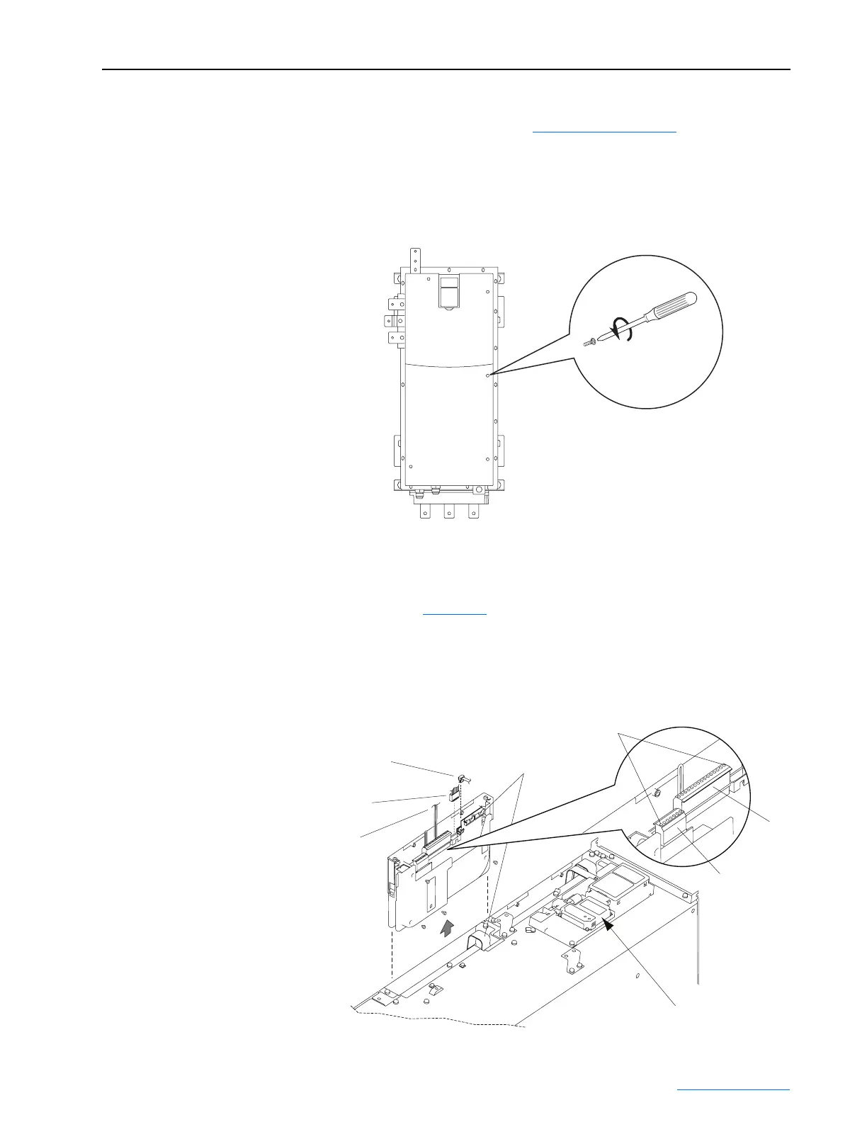
Removing the Drive Cover
Removing the Active
Converter Control Cassette
The Frame 2 regenerative-type drive is equipped with an Active Converter
control cassette. Figure 2.7
shows the location and removal of this cassette
to access its terminal blocks for control wiring. Refer to the PowerFlex 700
Active Converter Power Module User Manual (publication
PFLEX-UM002) for control wiring details.
Figure 2.7 Removing the Frame 2 Active Converter Control Cassette
(5 Captive Screws)
Internal DPI Cable
Synchronization Cable
(For use with 700 Vector Control only)
Synchronization Cable
(For use with 700S Phase II Control only)
40-Pin
Ribbon Cable
Pin 1
P2
Detail
P1
Communications
Adapter Option
 Loading...


