Frame 3A and 3B Installation 3-21
PowerFlex® 700L Liquid-Cooled Drive User Manual
Publication 20L-UM001D-EN-P
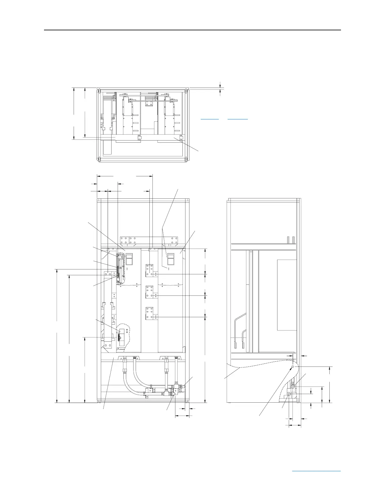
Figure 3.21 Locations for Frame 3B Complete Drive Control, Ground, Drive Input,
Motor Output, and Coolant Connections
Dimensions are in millimeters and (inches).
536 (21.09)
P1 & P2
24 (0.94)
Backplane of Power
Module Chassis.
Top Anti-sway
Bracket
559 (22.00)
TB5
Converter
Power Module
Inverter
Power Module
Power Module
Status Indicators
224 (8.82)
600 (23.62)
450 (17.72)117 (4.59)
P1
P2
Cutaway of Top Cover
Showing P1 and P2
Cutaway of
Bottom Cover
Showing TB5
1441 (56.72)
P1
1378 (54.27)
P2
706 (27.80)
925 (36.44)
51 (2.00)
157 (6.19)
231 (9.09)
231 (9.09)
275 (10.83)
Outlet
Right
Wall
Cutaway
Ø22 (Ø0.88) through
Knockout Size 1/2 inch
in Right Wall for Cooling
Loop Equipment Wiring
Outlet
InletBottom Anti-sway
Bracket
90 (3.56)
97 (3.81)
90 (3.56)
132 (5.18)
174 (6.87)
391 (15.38)
Inlet
See Figure 3.6 and Figure 3.20
for Inlet, Outlet, PE, and Motor
Lead Depth Dimensions
 Loading...


