3-20 Frame 3A and 3B Installation
PowerFlex® 700L Liquid-Cooled Drive User Manual
Publication 20L-UM001D-EN-P
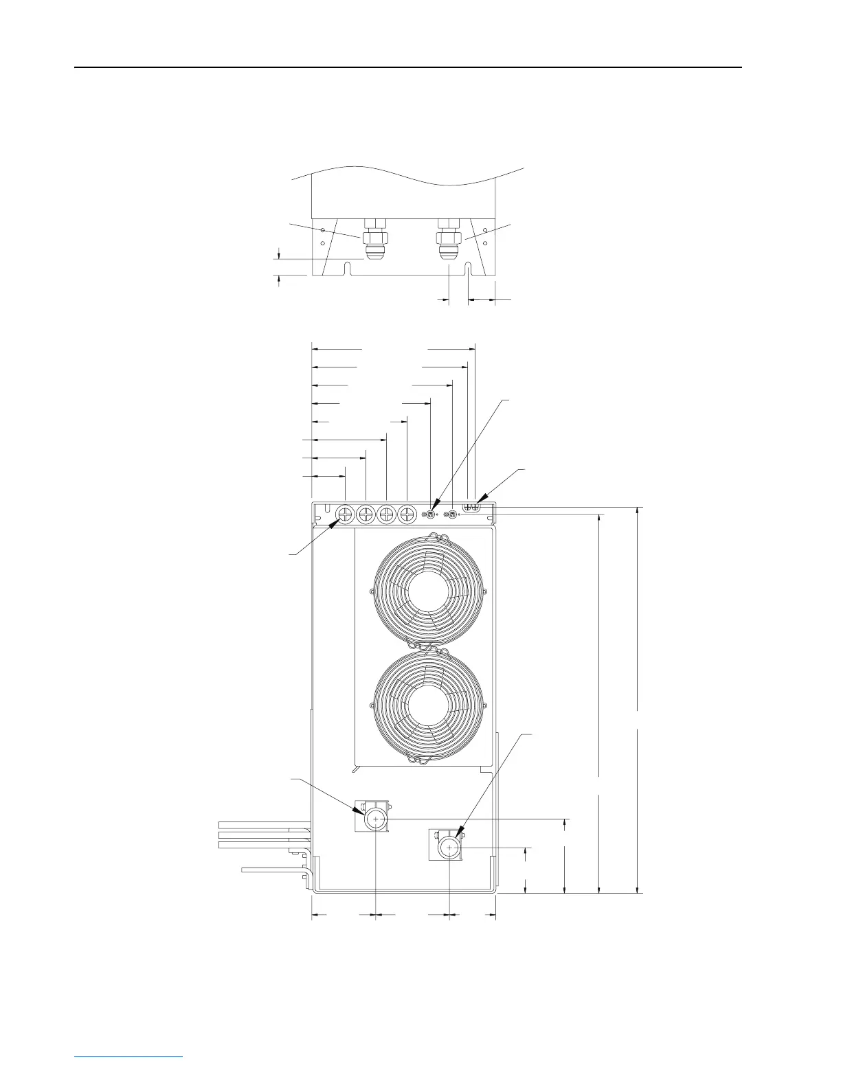
Figure 3.20 Frame 3A and 3B Power Module Locations for Control Wire Routing, DPI
Communications Ports/Cable Routing, and Coolant Connections
Control Wire
Routing Grommets
18.5 (0.73) Dia.
4 Places
DPI Communications Port (for module interconnection
and external HIM) 2 Places
Communications Cable
Routing Grommet
Note: For Active Converter Power Modules, connect
the cable to only one port. Operation of two cables from
the Active Converter Power Module is not supported.
Coolant
Inlet
Coolant
Outlet
Dimensions are in millimeters and (inches).
Bottom View of Power Module
108.1 (4.26)
78.2 (3.08)
48.2 (1.90)
91.1
(3.58)
67.5
(2.66)
106.5
(4.19)
66.3 (2.61)
107.6 (4.24)
549.0 (21.61)
559.5 (22.03)
138.1 (5.44)
171.9 (6.77)
203.6 (8.02)
225.7 (8.89)
236.4 (9.31)
23.9 (0.94)
28.0 (1.10)
39.5 (1.56)
Fluid Inlet
Fluid
Outlet
 Loading...


