Frame 3A and 3B Installation 3-19
PowerFlex® 700L Liquid-Cooled Drive User Manual
Publication 20L-UM001D-EN-P
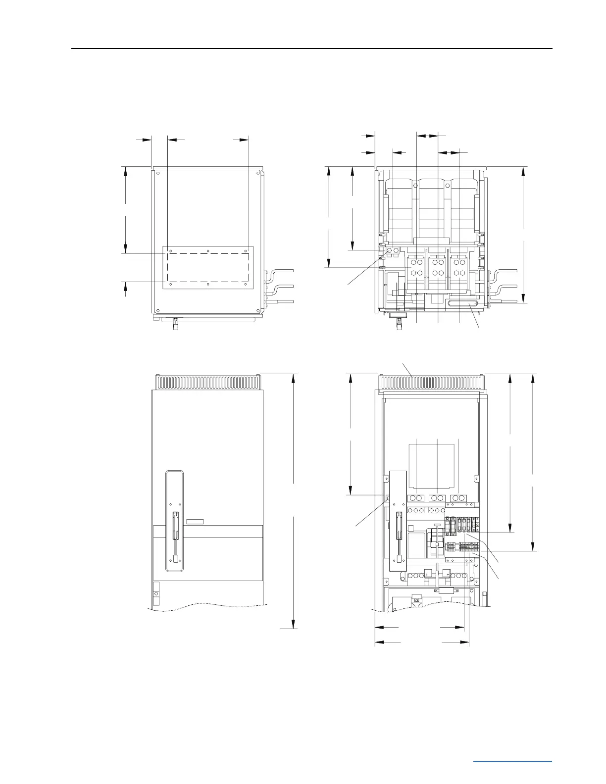
Figure 3.19 Location of Frame 3B Input Filter Bay Wire Routing
432 (17.00)
Cable Opening
Under Cover
152 (6.00)
Cable Opening
Under Cover
Installed
Vented Top Cover
464 (18.26)
87 (3.43)
224 (8.80)
114 (4.50)
114 (4.50)
730 (28.75)
95 (3.74)
448 (17.65)
540 (21.27)
647 (25.46)
847 (33.36)
946 (37.25)
477 (18.77)
504 (19.84)
PE
L1 L2 L3
L1 L2 L3
FU7, FU8, FU9
FU7, FU8, FU9, TB2
TB2
2286 (90.0)
Maximum
Installed Height
INSTALLED VIEWS CUTAWAY VIEWS
PE
Dimensions are in millimeters and (inches).
 Loading...


