4-2 Cooling Loop Installation
PowerFlex® 700L Liquid-Cooled Drive User Manual
Publication 20L-UM001D-EN-P
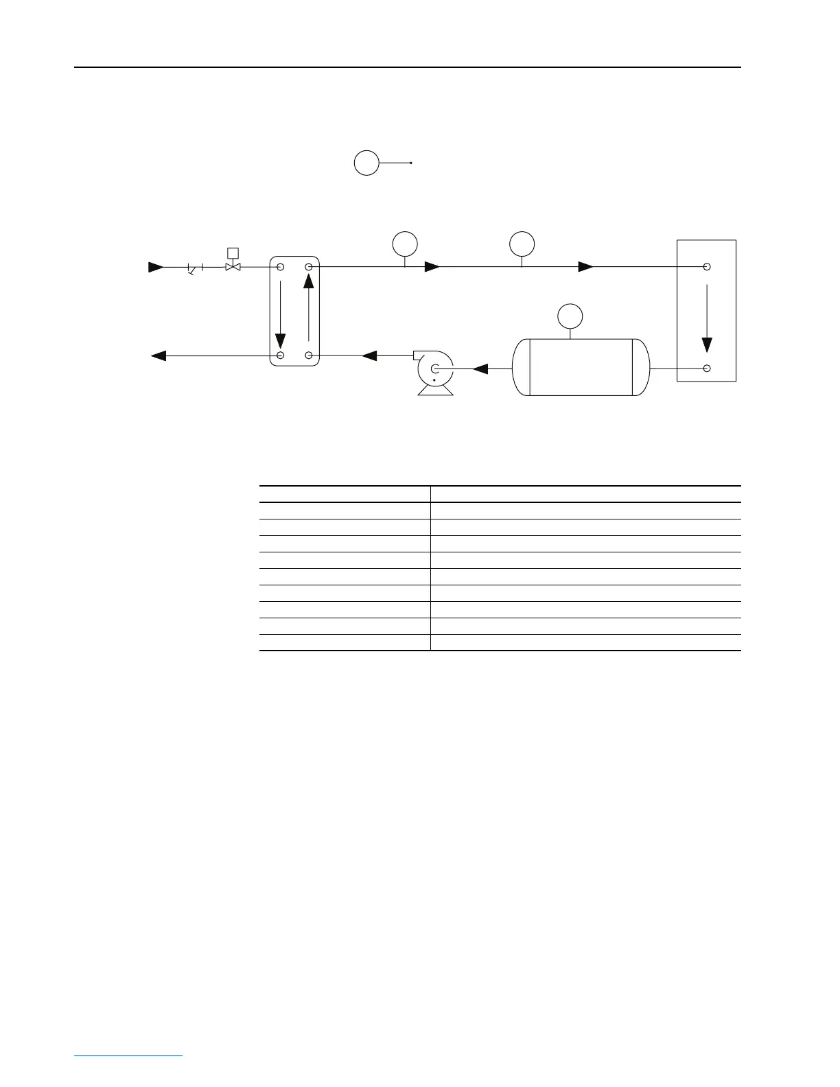
Figure 4.2 Liquid-to-Liquid Heat Exchanger Plumbing Diagram
The main components of the liquid-to-liquid heat exchanger cooling loop
include:
Ambient Sensor
Heat Exchanger
Pump
Reservoir
Drive
IN
OUT
IN
OUT
OUT
IN
Drive Coolant Temp.
Control
Valve
Strainer
Supply
Process
Water
Flow Switch
Level Switch
TE
TE FS
LS
Part Description
Strainer Filters particles from the supply water.
Control Valve Controls the supply loop water flow.
Heat Exchanger Plate Transfers heat from the drive loop to the supply loop.
Ambient Sensor Senses the ambient temperature used for the dew point control.
Drive Coolant Temperature Sensor Senses the drive coolant temperature used for the dew point control.
Drive Coolant Flow Switch Measures the drive coolant flow rate.
Level Switch Senses the level of coolant in the reservoir.
Reservoir Stores drive coolant.
Pump and Motor Circulates drive coolant.
 Loading...


