Frame 3A and 3B Installation 3-3
PowerFlex® 700L Liquid-Cooled Drive User Manual
Publication 20L-UM001D-EN-P
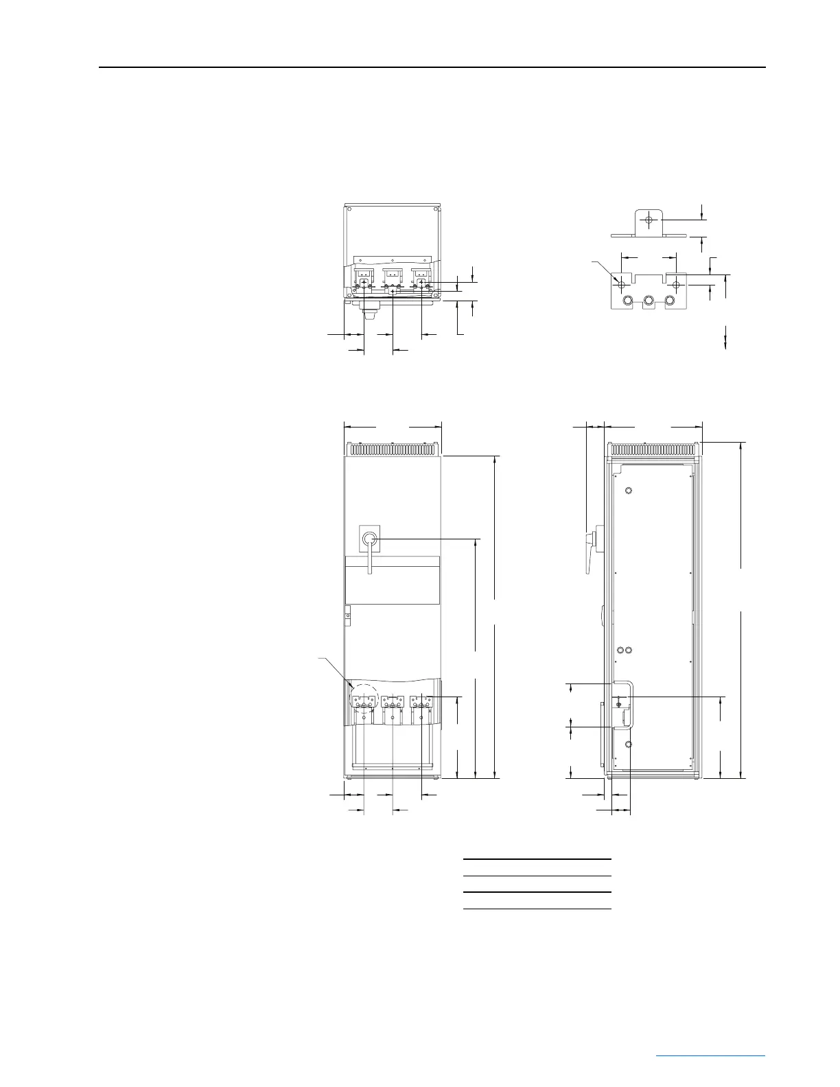
Figure 3.2 Frame 3A Input Filter Bay Power Wiring and Installation Dimensions
R/L1
S/L2
T/L3
Dimensions are in millimeters and (inches).
117.2
(4.62)
101.6
(4.00)
CABLE
CONNECTION DETAIL
31.8 (1.25)
19.0 (0.75)
507.7
(19.99)
125.2
(4.93)
177.8
(7.00)
177.8
(7.00)
607.3
(23.91)
113.5
(4.47)
605.0
(23.82)
2001.9
(78.82)
2087.2
(82.17)
Max
1487.0
(58.54)
507.7
(19.99)
267.7
(10.54)
321.6
(12.66)
507.7
(19.99)
46.5 (1.83)
114.4 (4.50)
125.2
(4.93)
58.5 (2.30)
Ø
12.7
(
Ø
0.50)
3 Places
177.8
(7.00)
177.8
(7.00)
See CABLE
CONNECTION
DETAIL
Approximate Weight kg (lbs.)
Input Filter Assembly
695 (1530)
 Loading...


