Rockwell Automation Publication 750-TG100B-EN-P - June 2019 111
Frame 7 Components Chapter 6
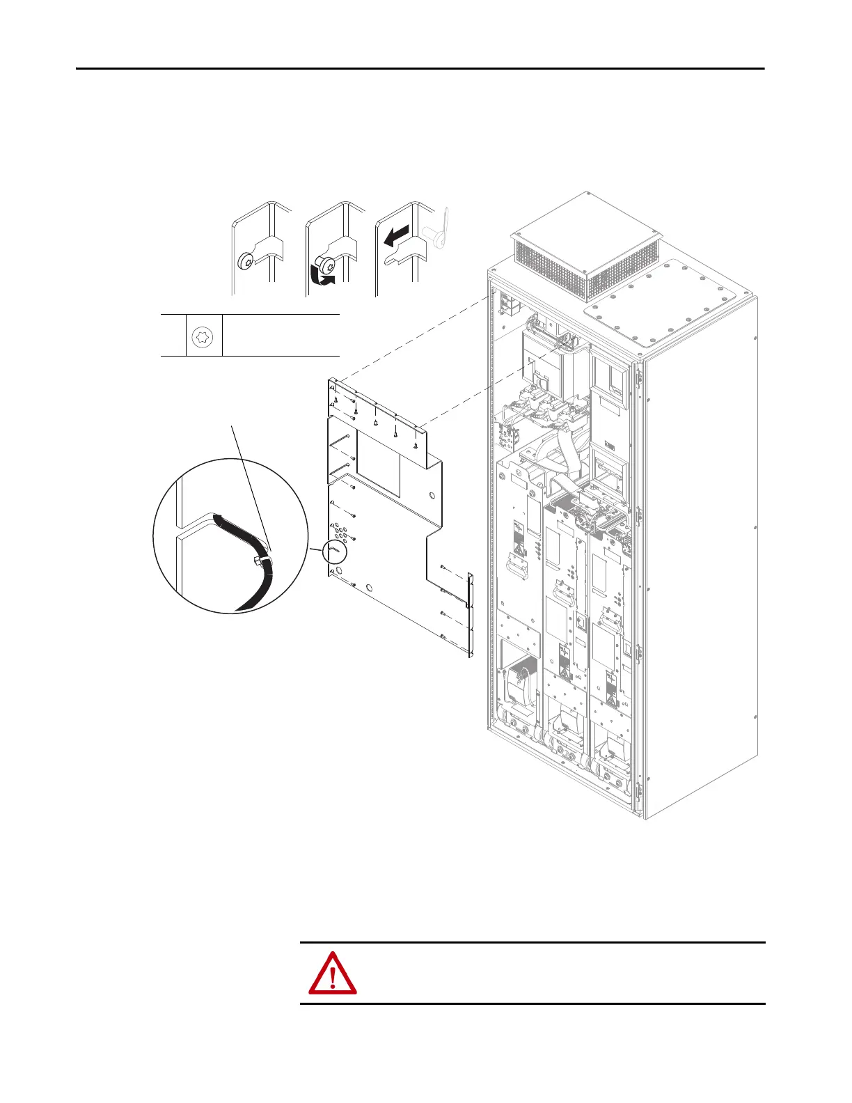
4. If a door-mounted HIM is installed, cut the cable tie that secures the HIM
communication cable to the guard.
5. Loosen the 16 M5.5 x 13 mm torx screws that secure the guard to the
enclosure and remove the guard. It is not necessary to remove the screws.
Install the Protective Guard
Install the protective guard in the reverse order of removal.
• Be sure to secure the HIM cable to the guard with a new cable tie.
5
M5.5 x 13 mm
T25
4.8 N•m (42 lb•in)
Screws shown removed for clarity only.
4. Cut the cable tie.
ATTENTION: To avoid an electric shock or burn hazard, never energize the drive
or bus supply with the protective guards removed.
 Loading...


