Rockwell Automation Publication 750-TG100B-EN-P - June 2019 243
Power Bay Components Chapter 9
8. Remove the four M12 x 13 mm hex nuts that secure the fuses to the DC
link bus bars and remove the fuses.
Install the DC Link Fuses
Install the DC link fuses in the reverse order of removal.
Power Module PE-B1 Power
Jumper Replacement
Replace the power module PE-B1 power jumper with kit catalog number
SK-RM-INV-JMPR-F8.
Remove the Power Module PE-B1 Power Jumper
Follow these steps to remove and replace the power module PE-B1 power jumper.
1. Review the Product Advisories on page 14
.
2. Remove power from the system. See Remove Power from the System on
page 15
.
3. Open the corresponding power bay enclosure door.
8
M12 x 13 mm
19 mm
45 N•m (398 lb•in)
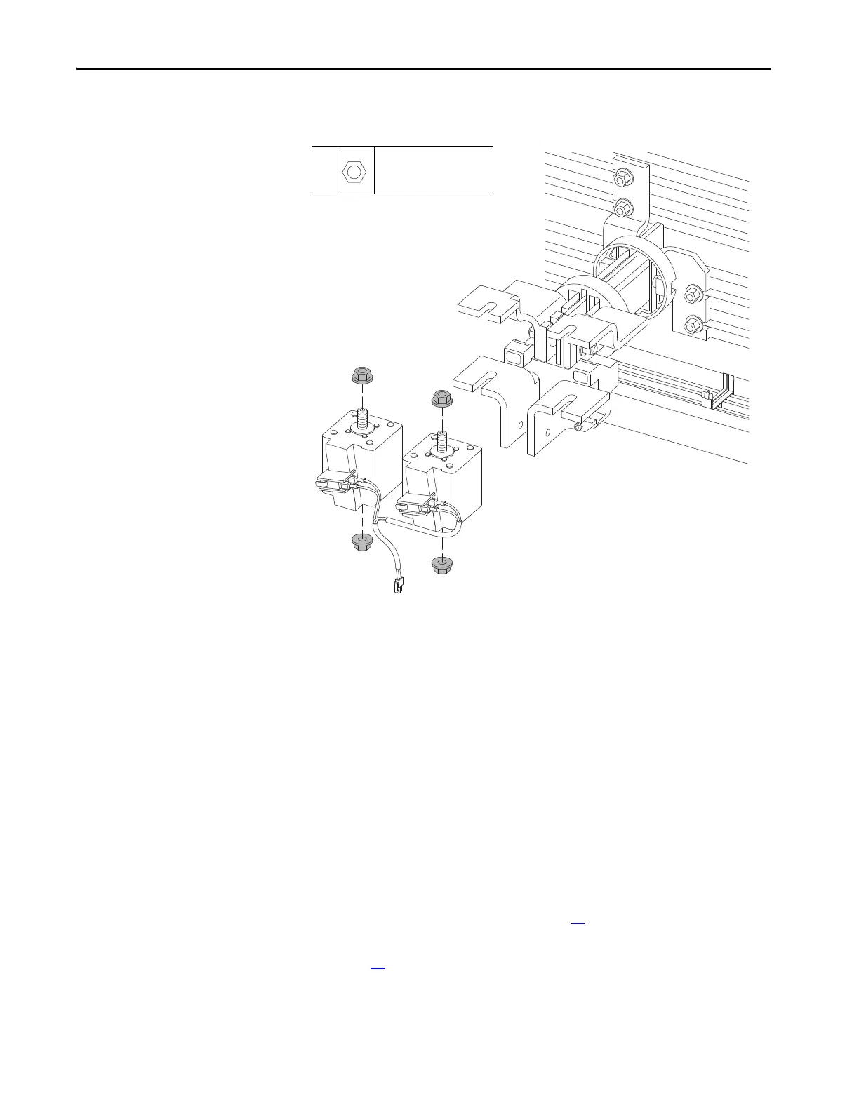
DC Link/Fuse and Bus Bar for
Single Power Module Shown.
 Loading...


