EasyManuals Logo

Rockwell Automation PowerFlex 755TR User Manual

Rockwell Automation PowerFlex 755TR
352 pages
To Next Page IconTo Next Page
To Previous Page IconTo Previous Page
Page #256 background imageLoading...
Page #256 background image
256 Rockwell Automation Publication 750-TG100B-EN-P - June 2019
Chapter 9 Power Bay Components
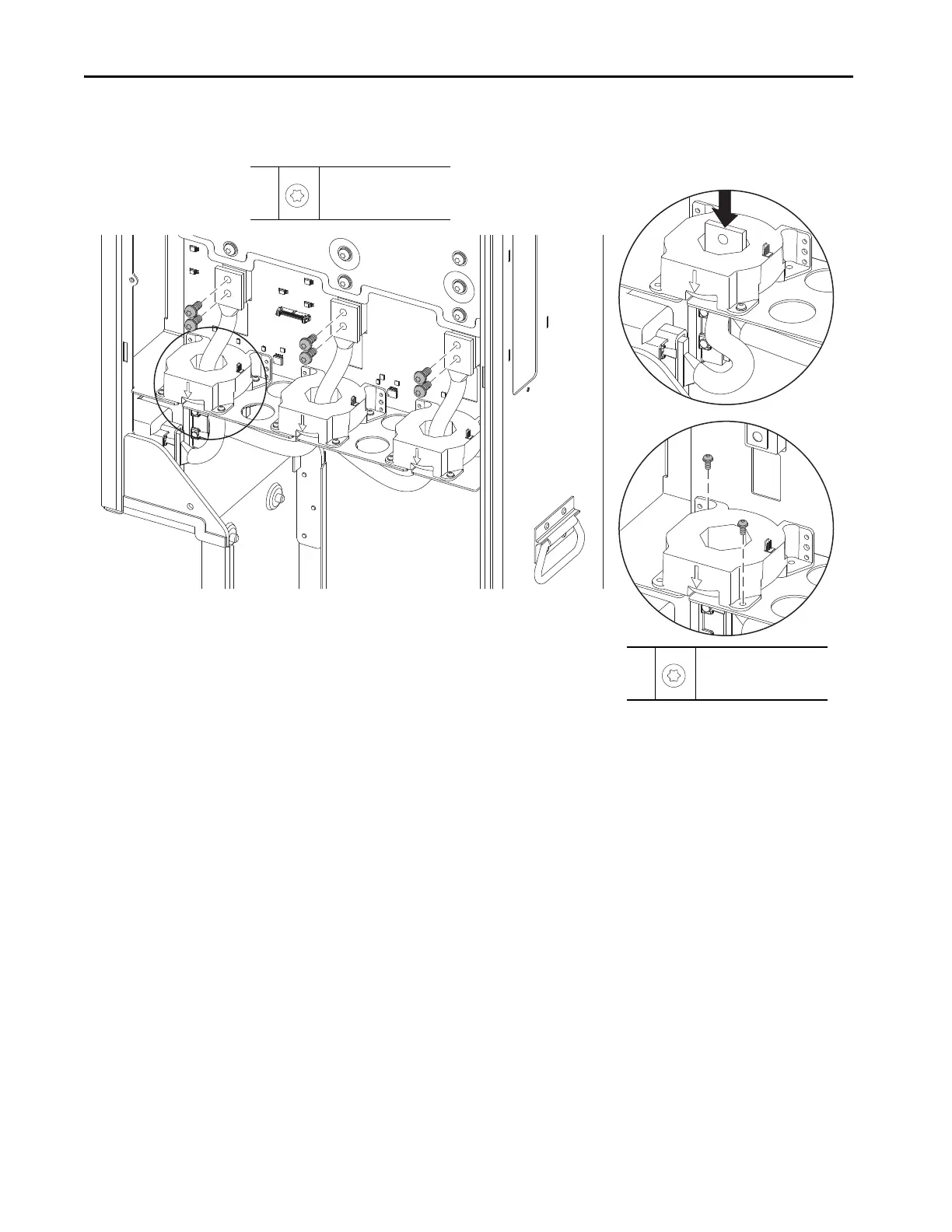
7. Remove the six M4 x 10 mm torx screws that secure the three current
sensors to the power module chassis and remove the current sensors.
Install the Current Sensors
Install the current sensors in the reverse order of removal.
6
M8 x 20 mm
T40
15 N•m (133 lb•in)
7
M4 x 10 mm
T25
2.6 N•m (23 lb•in)
Power Module without an Inductor Shown.

Table of Contents

Questions and Answers:

Question and Answer IconNeed help?

Do you have a question about the Rockwell Automation PowerFlex 755TR and is the answer not in the manual?

Rockwell Automation PowerFlex 755TR Specifications

General IconGeneral
BrandRockwell Automation
ModelPowerFlex 755TR
CategoryDC Drives
LanguageEnglish

Related product manuals