EasyManuals Logo

Rockwell Automation PowerFlex 755TR User Manual

Rockwell Automation PowerFlex 755TR
352 pages
To Next Page IconTo Next Page
To Previous Page IconTo Previous Page
Page #165 background imageLoading...
Page #165 background image
Rockwell Automation Publication 750-TG100B-EN-P - June 2019 165
Control Bay and Control Pod Components Chapter 7
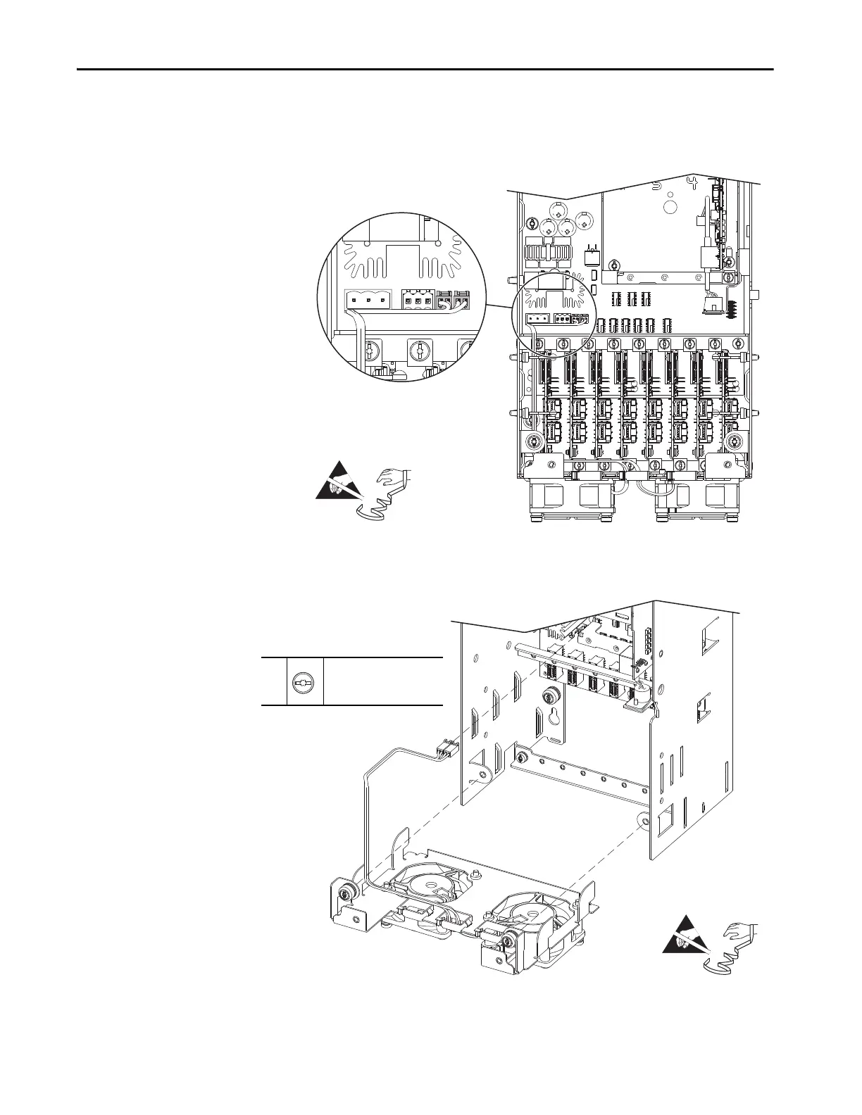
5. Disconnect the two fan power supply connectors from connectors J18 and
J25 on the fiber-optic interface board.
6. Remove the harness from the cable supports on the side of the pod chassis.
7. Loosen the two captive thumb screws on the fan assembly and pull the
assembly out and off the pod chassis.
J25
J18
=
7
–
T20 or F - 6.4 mm (0.25 in.)
2.6 N
•m (23 lb•in)
=

Table of Contents

Questions and Answers:

Question and Answer IconNeed help?

Do you have a question about the Rockwell Automation PowerFlex 755TR and is the answer not in the manual?

Rockwell Automation PowerFlex 755TR Specifications

General IconGeneral
BrandRockwell Automation
ModelPowerFlex 755TR
CategoryDC Drives
LanguageEnglish

Related product manuals