EasyManuals Logo

Rockwell Automation PowerFlex 755TR User Manual

Rockwell Automation PowerFlex 755TR
352 pages
To Next Page IconTo Next Page
To Previous Page IconTo Previous Page
Page #191 background imageLoading...
Page #191 background image
Rockwell Automation Publication 750-TG100B-EN-P - June 2019 191
Input Bay Components Chapter 8
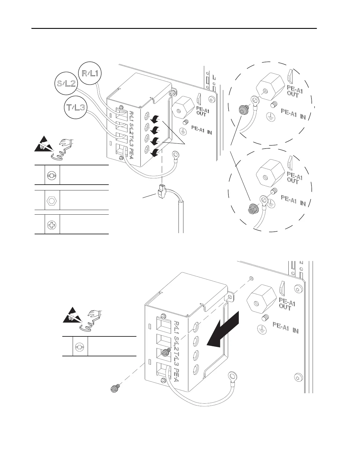
7. Loosen the terminal block screws that secure the wires to terminals
R/L1, S/L2, T/L3, and remove the wires.
8. Remove the two M4 x 10 mm slotted-torx screws that secure the TVSS
module to the panel and remove the module.
7
–
P2
4.0 N•m (35 lb•in)
5
M6 x 10 mm
T25
5.9 N•m (52 lb•in)
6
M6
10 mm
5.9 N•m (52 lb•in)
5
6
7
=
8
M4 x 10 mm
T20 or F - 6.4 mm (0.25 in.)
2.6 N•m (23 lb•in)
=

Table of Contents

Questions and Answers:

Question and Answer IconNeed help?

Do you have a question about the Rockwell Automation PowerFlex 755TR and is the answer not in the manual?

Rockwell Automation PowerFlex 755TR Specifications

General IconGeneral
BrandRockwell Automation
ModelPowerFlex 755TR
CategoryDC Drives
LanguageEnglish

Related product manuals