EasyManuals Logo

Rockwell Automation PowerFlex 755TR User Manual

Rockwell Automation PowerFlex 755TR
352 pages
To Next Page IconTo Next Page
To Previous Page IconTo Previous Page
Page #223 background imageLoading...
Page #223 background image
Rockwell Automation Publication 750-TG100B-EN-P - June 2019 223
Power Bay Components Chapter 9
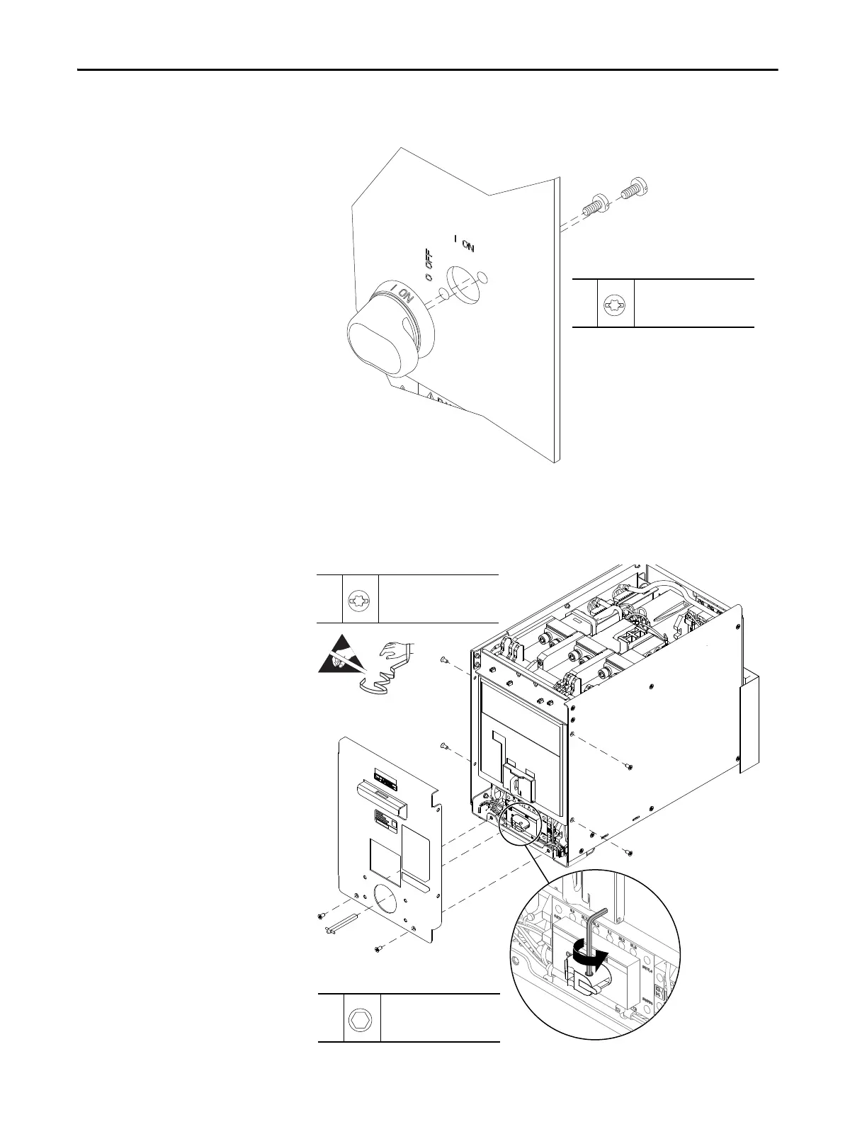
4. Remove the two M4 x 12 mm screws that secure the disconnect handle to
the door and remove the handle.
5. Remove the six M5 x 10 mm screws that secure the front cover to the DC
precharge unit and remove the cover.
6. Loosen the hexagonal screw that secures the disconnect handle shaft to the
disconnect switch and remove the handle.
4
M4 x 12 mm
T20
6.2 N
•m (55 lb•in)
5
M5 x 10 mm
T20
6.2 N•m (55 lb•in)
6
–
2.5 mm
0.6 N•m (5.4 lb•in)
=

Table of Contents

Questions and Answers:

Question and Answer IconNeed help?

Do you have a question about the Rockwell Automation PowerFlex 755TR and is the answer not in the manual?

Rockwell Automation PowerFlex 755TR Specifications

General IconGeneral
BrandRockwell Automation
ModelPowerFlex 755TR
CategoryDC Drives
LanguageEnglish

Related product manuals