88 Rockwell Automation Publication 750-TG100B-EN-P - June 2019
Chapter 5 Frame 6 Components
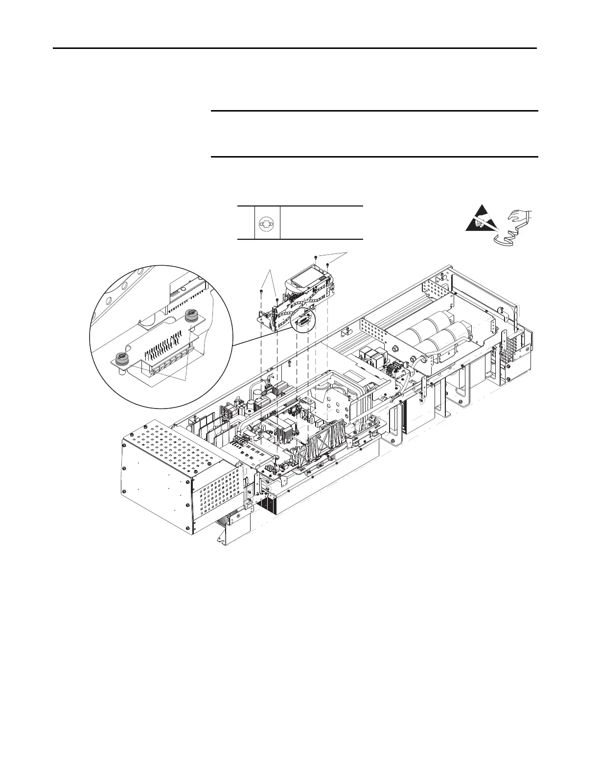
5. Remove the two M4 x 10 mm slotted torx screws that secure the HMI flex
circuit connector to the power interface circuit board.
6. Remove the four M4 x 10 mm slotted torx screws that secure the control
pod to the chassis and remove the control pod.
IMPORTANT The control pod contains a connector that connects to an edge connector on the
power feedback circuit board beneath it. Take care when lifting the control pod
off the chassis so circuit board damage does not occur.
6
6
5
5, 6
M4 x 10 mm
T20 or F - 6.4 mm (0.25 in.)
2.3 N
•m (20 lb•in)
 Loading...


