EN
67
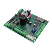
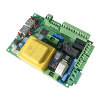
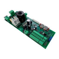
7 Commands and Accessories
If not installed, safety devices with NC contacts must be jumpered at the COM terminals,
or disabled by modifying the parameters , and .
For installations with two opposed barriers, connections for command signals and accessories
must be made on the MASTER controller. The sensing edge and, if used, the STOP command
signal must be connected to the SLAVE controller.
/)=
N.A. (Normally Open) .
N.C. (Normally Closed).
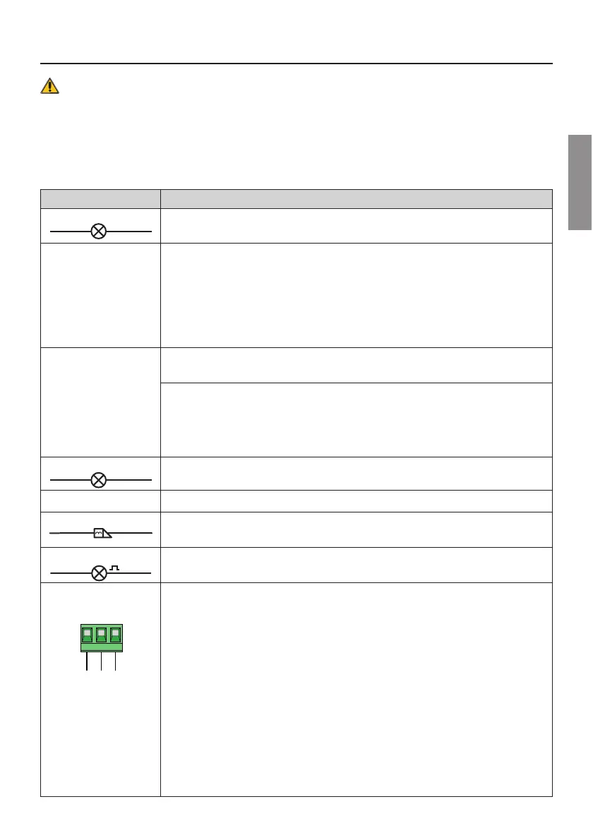
CONTACT DESCRIPTION
11(+SC) 10(COM)
Barrier open/closed indicator lamp, 24 V DC 3 W.
The function of the indicator lamp is determined by parameter $.
11(+SC) 13(COM)
4LSXSGIPPXIWXJYRGXMSRERHVFEXXIV]WEZMRKQSHIGSRRIGXMSRƼK
The power feed for the photocell transmitters (TX) may be connected to terminal 11(SC).
Set the parameter $ to enable the test function.
Each time a command is received, the controller unit switches the photocells off and on to check that
the contact changes state correctly.
Power feeds for all external devices (excluding the external radio receiver) may be connected to re-
duce battery consumption (if batteries are used). Set $ or $. In the case of installations with
two opposed barriers, the functions are not available for the SLAVE barrier.
WARNING! If contact 11(SC) is used for the photocell test function or battery saving function, a bar-
rier open indicator lamp CANNOT BE connected.
11(+SC) 13(COM)
Indicator lamp connection for signalling the ACS/BA/60 detachable boom system sensor anomaly or
for signalling battery supply anomaly (battery exhausted. (Fig. 9)
The voltage level of the battery can be set via parameter .
By connecting a RELAY to the SC output, an error alert signal contact can be achieved at an external
GSRXVSPW]WXIQƼK
NOTEMR1%78)670%:)W]WXIQWGSRRIGXXLII\XIVREPGSRXVSPW]WXIQXSXLISC output of the
MASTER control unit (if par. = , , ), the SC output of the SLAVE is of type "ON = bar open;
OFF = bar closed".
If par. = , the SC output of the SLAVE control unit provides instead an alarm signal relative to
the SLAVE barrier.
12(+LIGHTS) 13(COM)
Input for connecting ALED series signal lights on boom (optional). 24 V DC 12W max ƼK
14(+24V) 13(COM)
4S[IVJIIHJSVI\XIVREPHIZMGIWQE\;7IIXIGLRMGEPWTIGMƼGEXMSRW
15(+ES) 17(COM)
-RTYXJSVGSRRIGXMRKIPIGXVMGPSGO:HGQE\;SV;JSVIPIGXVSFPSGOTS[IVWYTTP]ƼK
The function of the electric lock is determined by parameter .
Vmedia=12Vdc, Vmax=40Vdc; see table "PRODUCT TECHNICAL FEATURES" on page 62
16(+LAM) 17(COM)
'SRRIGXMSRJSVƽEWLMRKPMKLX:('QE\;
8LIWIXXMRKWJSVXLITVIQERSIYZVIƽEWLMRK[EVRMRKWMKREPQE]FIWIPIGXIH[MXLTEVEQIXIV$, while
XLIƽEWLMRKQSHIMWWIX[MXLTEVEQIXIV.
1 8 ( C O M ) - 1 9 ( L N A ) -
20(LNB)
COM
LNA
LNB
18 19 20
RS485 serial communication cable connection (3x0.5 mm
2
- max. length 30 m) for installation of two
1%78)670%:)STTSWMRKFEVVMIVWJVSQƼVQ[EVIZIVWMSRQ or later).
Connections.
# Connect the COM-LNA-LNB terminals of the MASTER barrier to the relative terminals of the SLAVE
barrier.
# The MASTER barrier is the barrier which opens (completely) when the partial open command (PED)
is received.
# Set parameter $ for the MASTER barrier and parameter $ for the SLAVE barrier.
# %JXIVLEZMRKQSHMƼIHXLIWIXXMRKWSJTEVEQIXIV$ shut off power and power up again.
# All command signals, the photocells and the main STOP command must be connected to the
MASTER barrier. The sensing edges and the ACS/BA/60 BreakAway devices must be connected
to the corresponding barriers.
# An auxiliary STOP command signal may also be connected to the SLAVE barrier. If not used, jumper
terminals 21(ST)-22(COM) on the SLAVE controller.
# All parameters except for $, and must be set on the MASTER controller.
# The travel acquisition procedure must be performed for both barriers, after setting the parameters
as required and in accordance with the type of installation.
# Alarm messages are viewable on the displays of the respective controllers.