Instrument Design and Function Description R&S CMU
1100.4903.82 3.24 E-5
An Ethernet interface is available for data input and output (Option R&S
CMU-B87).
An RS232 interface is available for debugging.
An AT-bus interface is used for control and data communication with the
front module computer.
1xEV-DO Module
R&S CMU-B89
The Option 1xEV-DO Module R&S CMU-B89 is designed as sandwich
module and is directly plugged onto the CDMA2000 SIGN. UNIT Var22.
This option permits to generate 1xEV-DO Signaling signals.
Speech Codec Module
R&S CMU-B85 Var22
The Option SPEECH CODEC R&S CMU-B85 Var22 is designed as
sandwich module and is directly plugged onto the CDMA2000 SIGN. UNIT.
This option permits to read in and output analog speech signals
(handsetin/out lines) via A/D and D/A converters.
Message Monitor
R&S CMU-B87
This Option Message Monitor R&S CMU-B87 is designed as a cable to
connect the CDMA2000 SIGN. UNIT with the rearpanel of the R&S CMU
LH_3GPP2.DRW
FPGA
A
D
Power PC
MPC8540
Dig. I/Q-IN
TX-I
Control-/
Sync-Bus
ISA-Bus
CMU-B85 Var22
Speech Codec Module
Netclk CLK-
Distrib.
3GPP2-Linkhandler
PPC-PCI-Bus
Ethernet
A
D
TX-Q
Dual-Port-RAM, Registers,..
FLASH
32M x 16
DDR-SDRAM
Local-Bus
700 MHz
(32 Bit/33MHz)
(32 Bit)
RS232
Test
5V
3V
5V
3V
ISA-Interface
(Buffer + Register)
AFGENMON
Handset In
Handset Out
32Mx64
AWGN-
SSRAM
512Kx36
Power-PC-Module
CMU-B89
1xEVDO-Module
Signaling
FIR
FIR
Test/
LED/
Debug
XC2V2000
DC
DC
+5V
SUP_FPGA
SUP_MODUL
SUP_MODUL
+1.5V
+1.5V
+1.2V
Codec
SUP_DSP
+1.8V
MUX
MUX
Ethernet
Ethernet
CSM 5000
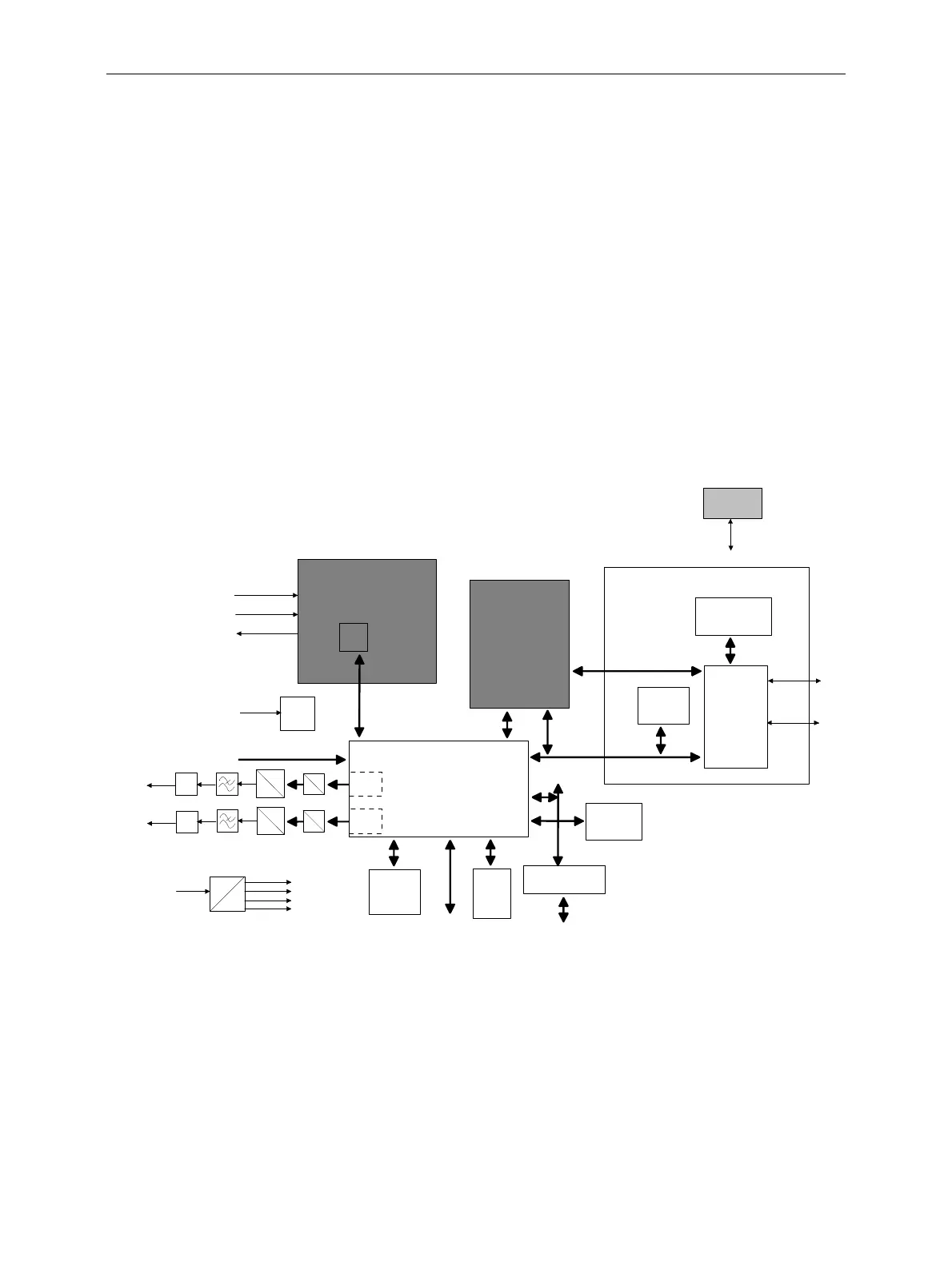
Figure 3-4: CDMA2000 Var22 Signalling Unit block diagram

 Loading...


