28
Subject to change without notice
Short description HMP4030 / HMP4040
4 Operation of the HMP4030 / HMP4040
4.1 First time operation
Prior to the fi rst time operation please note and observe the
safety instructions given above!
Switching on
Turn the instrument on by pushing the POWER button
1
. After
turn-on the HMP4030/4040 will restart in the same operating
mode it was in when it was switched off. All instrument settings
are stored in a nonvolatile memory and are recalled upon turn-on.
As a rule, all outputs ( OUTPUT) will be disabled upon turn-on in
order to prevent inadvertent application of voltage to a load which
might destroy it by too high a voltage or current due to settings
previously stored.
4.2 Selection of channels
Select the channels by pressing the associated pushbuttons
CH1
6
, CH 2
7
, CH3
10
or CH4
14
. After pressing the buttons the
channel LEDs will light up green. All subsequent settings will refer
to the channels selected. If no channels were selected the LEDs
will remain dark. It is recommended to fi rst set the desired voltages
and currents before the outputs will be activated simultaneously
by pressing the OUTPUT button
18
. (see Activation of channels) If
the button OUTPUT
18
is activated it will light up white.
4.3 Adjustment of output voltage
First press the button VOLTAGE
11
before the voltage of a channel
can be adjusted by pressing the button CH1
6
, CH 2
7
, CH3
10
or CH4
14
. If the button VOLTAGE
11
is activated it will light up
white, the colour of the selected channel will change to blue. The
white LEDs of the arrow buttons
3
will also light up if either the
button VOLTAGE
11
or the button CURRENT
9
is activated. The
value of the output voltage can be set either by using the turning
knob
4
, the numerical keyboard
5
or the arrow buttons
3
.
The simplest method of entering voltage parameters quickly and
exactly is the entry via the numerical keyboard
5
. When entering
the voltage value via the keyboard the value will be accepted upon
pushing the ENTER button
8
. Prior to pushing any such key an
entry may be deleted by pushing the „–“ key.
When using the knob
4
fi rst press VOLTAGE
11
and select the
decimal position to be adjusted with the arrow buttons
3
. Turning
the knob cw, the voltage will be increased, turning it ccw, it will be
decreased. After the adjustment with knob or numerical keyboard
is completed it will be stored by pressing VOLTAGE
11
again,
otherwise the instrument will exit this mode automatically after
5 sec. without storing the input. The following picture shows the
maximum values which can be set for each channel.
Fig. 4.1: Available maximum values of HMP4040
Due to their electrically insulated, earth free, overload and short
circuit proof outputs, they can be operated in series or in parallel
to deliver high voltage or high current output. A basic prerequisi-
te is the use of separate electronic fuses, which can be logically
combined (FuseLink) to shut down linked channels in case of a
fault condition, according to the user’s setup (e.g. CH1 follows
CH2 and CH3 follows CH1 or CH2). Special emphasis has been
put on a comfortable and practice oriented tracking function.
If necessary, the corresponding channels are selected prior to
a voltage or current change and altered in common
Fig. 3.3: Arbitrary voltage step
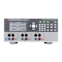
The series HMP has a 3-lines (HMP4030) resp. 4-lines
(HMP4040) LCD-Display (240 x 128 pixel). A compact unit size
and the availability of all outputs (including sense terminals)
on the rear side facilitate the integration into 19” rack mount
systems. The HMP series is equipped with a electrically insu-
lated USB/RS-232 dual interface. Optionally, an Ethernet/USB
or GPIB (IEEE-488) interface is available.
Fig. 3.2: Fuse Linking aktivated
Fig. 3.4: Outputs on the rear panel
 Loading...