30
Subject to change without notice
Extended functions
5 Extended functions
5.1 Storing/recalling settings ( STORE/ RECALL)
The present instrument settings can be stored in any of the
locations 0 to 9 of a nonvolatile memory by pressing the button
STORE
19
; the location is selected with the knob
4
. Use the
button RECALL
17
to recall the settings; use the knob
4
for the
selection of the location. If any of the buttons STORE or RECALL
is activated it will light up white.
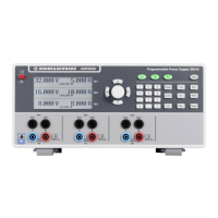
5.2 Tracking function
The tracking function allows to lock several channels together
so they track each other. It is possible to adjust as well the
voltages as the current limits of the individual channels simul-
taneously. The following picture shows an example: the 1 V
decimal position of all 3 channels is selected.
Press the TRACK button
15
to activate the tracking mode; then
the individual channels can be selected. If, e.g., after pres-
sing the VOLTAGE button
11
, the voltage is adjusted with the
knob
4
or the arrow buttons
3
, the voltages of the selected
channels are changed by the same amount. The same applies
to the currents if the CURRENT button
9
was pressed. The
HMP4030/4040 keeps the voltage resp. current differences
between the channels constant unless any of the channels
transgresses the minimum or maximum value of voltage or
current. As long as the tracking function is active the button will
light up white; the function will remain active until the button
was depressed again (no automatic reset after 5 sec).
5.3 Menu options (MENU)
The menu is entered by pressing the MENU button
12
. The
following options are available:
5.3.1 FUSE Linking
Fig. 5.3: Activated Fuse linking shown in the display
The function fuse linking allows to link individual channels to-
gether. The channels can be selected or deselected by a center
click of the knob. Press MENU
12
to revert to the display (no auto-
matic reset after 5 sec). The left arrow button
3
is used to return
to the previous menu level. If the electronic fuse was activated for
one channel by pressing FUSE
13
and if the current of this channel
exceeds the current I
max
preselected all channels will be switched
off which were linked to this channel.
Fig. 5.4: FUSE Linking
Fig. 5.4 shows how exceeding the current limit
of CH1 will automatically cause switching off of
channels CH2 and CH3 while exceeding the current
limit of CH2 only causes switching off of CH3.
If the electronic fuse switched the channels linked off the OUPUT
button
18
remains active. The channels can be reactivated any
time by pressing the associated channel buttons, however, they
will only come on again after the current decreased below the
preset limit I
max
.
Fig. 5.2: HMP4030/40 main menu overwiew
Main-Menu HAMEG HMP4030 / HMP4040
–> Fuse Linking
–> Arbitrary
Transfer Waveform
Start Waveform
Stop Waveform
Edit Waveform
Arbitrary Editor
Save Waveform
Recall Waveform
–> Over Voltage Protection (OVP)
–> Interface
Select Interface
Settings
Information
–> Display & Key Brightness (1 – 8)
–> Display Contrast
–> Beeper
ON
OFF
Only Critical Events
–> Information
–> Reset Device
No
Yes
Fig. 5.1: 1 V decimal position of all three channels
 Loading...