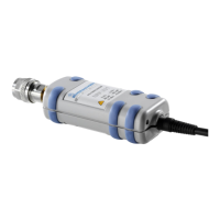
R&S NRP-Z91 Unpacking the power sensor
1168.8579.12 1.1 E-6
1 Putting into Operation
Follow the instructions below precisely to prevent damage to the power sensor –
particularly when you are putting it into operation for the first time.
Unpacking the power sensor
Remove the power sensor from its packing and check that nothing is missing. Inspect all items for
damage. If you discover any damage, inform the carrier responsible immediately and keep the packing
to support any claims for compensation.
It is also best to use the original packing if the power sensor is to be shipped or transported at a later
date.
The power sensor contains components which can be destroyed by electrostatic
discharges. To prevent this from happening, never touch the inner conductor of the RF
connector and never open the power sensor.
Connecting the power sensor
To prevent EMI, the sensor must never be operated with its enclosure wholly or partially
removed. Only use shielded cables that meet the relevant EMC standards.
Never exceed the maximum RF power limit. Even brief overloads can destroy the sensor.
In many cases, the RF connector only requires manual tightening. However, for maximal
measurement accuracy, the RF connector must be tightened using a torque wrench with a
nominal torque of 1.36 Nm (12" lbs.).
Operation with the R&S NRP/NRP2 power meter
Connecting the power sensor
The power sensor can be connected to the R&S NRP/NRP2 base unit when it is in operation. The
multiple circular plug-in connector must be inserted, red marking upwards, into one of the
R&S NRP/NRP2 base unit’s sensor connectors. When the power sensor is connected, it is detected by
the R&S NRP/NRP2 base unit and initialized.
The power sensor R&S NRP-Z91 has a male N connector and so can be connected to any standard
female N connector. Using light pressure, and keeping the male N connector perpendicular, insert it into
the female N connector and tighten the N connector locking nut (right-hand thread).
 Loading...


