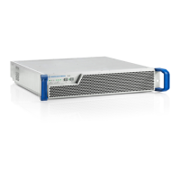
Transmitter System R&S TLx9
R&S
®
TLx9
57System Manual 2506.5060.02 ─ 03
●
R&S TLx9 all-in-one transmitter system, integrated in a 19” x 1 or 2 HU housing
(depending on the type)
●
Short-circuit connector for X6
●
Power cable (type depending on the target country)
●
User documentation
●
Delivery notes
3.2.1.2 Unpacking Instrument
Carefully remove the instrument from the carton and check the delivery for complete-
ness against the delivery note.
3.2.1.3 Setting Up Instrument
The instrument can be built into a 19“ rack. Depending on the transmitter type, 1 or 2
height units are required for installation.
Make sure the transmitter is firmly fixed in the rack and there is sufficient ventilation.
Make sure in particular that the flow of air through the inlets and outlets is not obstruc-
ted.
3.2.2 Connecting Cables
Always make sure that the power supply is disconnected before connecting any devi-
ces. This will prevent injuries and damage to the devices.
The cables used to provide ASI, 10 MHz, PPS and GPS signals should be double
shielded.
IP and Ethernet connections should use double shielded class CAT6 cables.
The optional R&S TDU900/901 display unit is connected to the USB Interface, using
an USB 2.0 cable provided by Rohde & Schwarz. Any other cables are not allowed.
The RF cable for the optional satellite receiver should have a minimum screening
attenuation of 1
10 dB.
Installation R&S TLx9

 Loading...