Home
Rohde & Schwarz
Transmitter
SR8000 Series
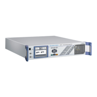
Rohde & Schwarz SR8000 Series User Manual
4
of 1
of 1 rating
199 pages
Give review
Manual
Specs
To Next Page
To Next Page
Loading...
5300.9677.72 -4
- 0.1 -
Broadcasting Division
System Manual
R&S
®
SR8000 – FM Transmitter
VHF, Solid-State Low-Power
All activities connected wit
h installing, starting up
, operating, maintaining,
troubleshooting, an
d servicing the descr
ibe
d system must be car
ried out by specialist
technicians only.
Printed in Germany
2
Table of Contents
R&S Sr8000
6
Table of Contents
6
Table of Contents
10
About this Manual
11
Chapter 1
11
Safety Instructions for Transmitter Systems and Equipment
12
General Safety Instructions
13
Special Hazard Information
14
Hazards from AC Supply Voltage
14
AC Supply
14
Emergency-Off System
14
Replacing Fuses
14
Opening the Transmitter
15
Hazards from High Energy Circuits
15
Hazards from RF Radiation
16
Antenna Connector
16
Obligation to Instruct Personnel
16
RF Shielding
16
Rules of Conduct for Transmitter Operation
17
Rules of Conduct for Working on Open Transmitters
17
Risk of Lightning Strike
17
Fire Risk
18
Hazards from Beryllium Oxide (Beo) Ceramics
18
Identification of Parts Containing Beo Ceramics
19
Measures for Dealing with Breakage and Disposing of Waste
19
Rules of Conduct for Working with Beo Ceramics
19
Design and Function
22
Design and Function/Specifications
24
Chapter 2 Design and Function
25
Mechanical Design
26
Mechanical Design: Base Unit
26
Mechanical Design: Separate Amplifier
32
Connections
33
Rear Panel Connections: Base Unit
33
Rear Panel Connections: Separate Amplifier
36
Front Panel Connections: Base Unit
37
Front Panel Connections: Separate Amplifier
38
Elements on the Front Panel
38
Input Screen
38
Function Keys and Displays: Base Unit
39
Displays: Separate Amplifier
40
Specifications
42
Protection of Electrical System
43
Power Failure
43
Power Supply Fault (R&S SR8010)
44
Power Supply Fault (R&S SR8025/SR8050/SR8100)
44
Power Supply Fault (R&S SR8130)
45
Damage on RF Output Side
46
Power Supply Fault (R&S VU813)
46
Protection against Overvoltages from the Antenna Cable
47
Mechanical Loading
48
Protection of Air Supply
48
Installation
50
Equipment Supplied/Cabling
52
Chapter 3
53
Equipment Supplied
53
Cabling
54
AC Power Supply
54
Connecting Transmitter Ground
54
AC Supply
55
Rear Panel Connections
55
Rear Panel Connections (Separate Amplifier)
58
R&S SR8250A: Connecting Standalone Instruments
59
Front Panel Connections
60
Front Panel Connections (Separate Amplifier)
61
Putting into Operation
62
Operation
64
Chapter 4 General Information
65
Preparations
65
Requirements
65
Operating the Transmitter
66
Putting a Transmitter into Operation
67
Preparing for Local Operation
67
Checking and Setting System and Operating Parameters
67
Changing the User Type
67
Configuring R&S SR8250A System
68
Entering Default Settings
68
Configuring Transmitter Standby and Remote-Control Interface
69
Configuring Rear Panel Ethernet Connection
70
Setting Modulation-Specific Parameters
71
Selecting the Modulation Mode
71
Setting Pilot Tone and Preemphasis
73
Setting the Nominal Deviation, Configuring the Limiter
74
Deviation and MPX Limiters
76
Setting Input Impedances for Analog AUDIO
77
Setting the Audio Parameters
77
Entering Settings for Digital Audio
78
Setting the Parameters for the aux Inputs (Incl. RDS)
79
Setting the Transmission Frequency
80
Entering Output Stage Settings
80
Setting Output Power Thresholds
80
Setting the Output Stage
81
Completing Procedure for Putting Transmitter into Operation
83
Checking the Status Displays
83
Checking the Exciter Status Displays
83
Checking the Transmitter Status Display
83
Checking the Output Stage Status Display
85
Clearing Event Memories
85
S Netccu800 Setup for 1+1/N+1 Systems with R&S SR8000
87
General Information/Transmitter Menus
90
Authorizations and Menu Levels
92
Authorizations
92
Chapter 5 General Information
92
Maintenance
93
Local Operation
94
Navigation
95
Operating Structure
95
Selecting and Editing Entries
97
Context Menu
98
Operation from a PC or Via Remote Control
99
Installation and Configuration
100
Browser-Based Operation
103
User Administration
106
Creating, Changing and Deleting Users
107
Closing Active Sessions
109
Transmitter Menus
111
Overview of Menus
111
Status Menu Window
113
Operation Menu Window
114
Logbook Menu
115
Logbook Context Menu
116
Summary Menu Window
116
Setup > Common Menu Window
117
Setup Menu
117
Setup > Ethernet Menu Window
118
Setup > System Menu Window
118
Setup > RS232 Menu Window
119
Setup > SNMP > General Menu Window
120
Setup > SNMP Menu
120
Setup > SNMP > Manager Menu Window
121
Setup > SNMP > Alarmsinks Menu Window
122
Device Info Menu
123
Setup > Bitbus Menu Window
123
Device Info > Device Menu Window
124
Device Info > Exciter FM Board Menu Window
124
Servicing
124
Device Info > Mainboard Menu Window
125
Device Info > Boot Flash Menu Window
126
Device Info > Processor Board Menu Window
127
Exciter > Status > Overview Menu Window
127
Exciter > Status Menu
127
Exciter Menu
127
Exciter > Status > Exciter FM Board Menu Window
130
Exciter > Status > Analog Status Menu Window
131
Exciter > Status > Digital Status Menu Window
132
Exciter > Input > Analog Audio Menu Window
134
Exciter > Input Menu
134
Exciter > Input > Digital Audio Menu Window
136
Exciter > Input > Data Input Menu Window
137
Exciter > Input > Automatic Input Menu Window
138
Exciter > Modulation Menu Window
141
Exciter > Deviation/Limiter Menu Window
142
Deviation and MPX Limiters
144
Exciter > RF Menu Window
145
Exciter > Static Delay Menu Window
146
Static Delay Function Applications
147
Output Stage > Status Menu Window
148
Output Stage Menu
148
Outputstage > Measurements > Combiner Menu Window
150
Outputstage > Measurements > Internal Amp Menu Window
150
Outputstage > Measurements Menu
150
Outputstage > Measurements > External Amp Menu Window
152
Output Stage > Limits Menu Window
153
Output Stage > Setup Menu Window
153
Parameter Set Menu Window
154
Table of Contents
172
Chapter 8
173
Necessary Tools and Test Equipment
173
Removable Transmitter Components
174
Replacing Fan
175
Removing the Fan
175
R&S Sr8010
175
R&S Sr8025/Sr8050/Sr8100/Sr8130/Vu813
176
Installing the Fan
178
Replacing Fuses on the Power Supply
179
R&S Sr8010
179
R&S Sr8025/Sr8050/Sr8100
180
Switching on the Automatic Circuit Breaker
183
R&S Sr8130/Vu813
183
Interface Description
186
Chapter 9 Interface Description
187
ETHERNET (X50) - Control Interface for Local (RJ45): Connector, Female, 8-Pin
187
Front-Panel Interfaces
187
TEST (X60) - Test Output: SMA Connector
187
ETHERNET (X6) - Control Interface (RJ-45 Remote): Connector, Female, 8-Pin
188
RF (X7) - RF Test Output FM: SMA Connector
188
X1 - AC Supply Feed
188
X23A - Code: D-SUB Connector, 9-Pin
189
X23B - RF Loop: D-SUB Connector, 9-Pin Male
189
X22A - Remote-Control Interface for Commands/Messages: D-SUB Connector, 25-Pin Male
190
X22B - AMP Interface to External Amplifier: D-SUB Connector, 25-Pin
191
X11R - AF Input Right: XLR Connector
192
X11L - AF Input Left (Alternative MPX): XLR Connector
193
X12 - AUX1/RDS Input (BNC)
193
X21 - Input AES/EBU (Alternative MPX): XLR Connector
193
X13 - Output Pilot: BNC
194
X14 - AUX2 Input (BNC)
194
X8 - Seconds Pulse from External GPS Receiver (BNC, Reserved)
194
X9 - 10 Mhz External Reference (BNC, Reserved)
194
X2 - RF Output FM: N or 7/16 Connector
195
X31 - Fan E1
195
X32 - Fan E2
195
X5 - GPS Antenna (BNC, Reserved)
195
4
Based on 1 rating
Ask a question
Give review
Questions and Answers:
Need help?
Do you have a question about the Rohde & Schwarz SR8000 Series and is the answer not in the manual?
Ask a question
Rohde & Schwarz SR8000 Series Specifications
General
Brand
Rohde & Schwarz
Model
SR8000 Series
Category
Transmitter
Language
English
Related product manuals
Rohde & Schwarz SR8010
199 pages
Rohde & Schwarz SR8050
199 pages
Rohde & Schwarz SU 4200
142 pages
Rohde & Schwarz SCV8000E/R
214 pages
Rohde & Schwarz TLx9 Series
90 pages