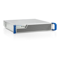
Transmitter System R&S TLx9
R&S
®
TLx9
61System Manual 2506.5060.02 ─ 03
2. Alternatively, feed the 1 pps signal of an external reference source via X23 (1PPS
IN)
3.2.2.4 Connecting Antenna System
Risk of RF burns
Before connecting the antenna cable, make sure that the instrument cannot output RF
at the output.
For EMC reasons, only cables with double shielding are to be used at the RF output.
Connect the antenna system to X60 (RF Output).
3.2.2.5 Preparing RF Carrier Loop
Risk of RF burns
Before putting the instrument into operation, make sure that the available interlock loop
systems are in use.
●
Prepare the interlock loop system (if available) for connection to X6 (TX IF)
●
If no interlock loop devices are available in the transmitter system (only permissible
with low power), have the supplied short-circuit connector at the ready
The interlock loop is only closed after (!) startup via X6 (TX IF), after which the instru-
ment can then produce RF
3.2.2.6 Connecting User Interface
For operating the system, it is possible to connect the transmitter to a PC, using an
Ethernet link via RJ-45 connector X7 (LAN LOCAL).
For connection to a remote monitoring network use RJ-45 connector X2 (LAN
REMOTE).
Installation R&S TLx9

 Loading...