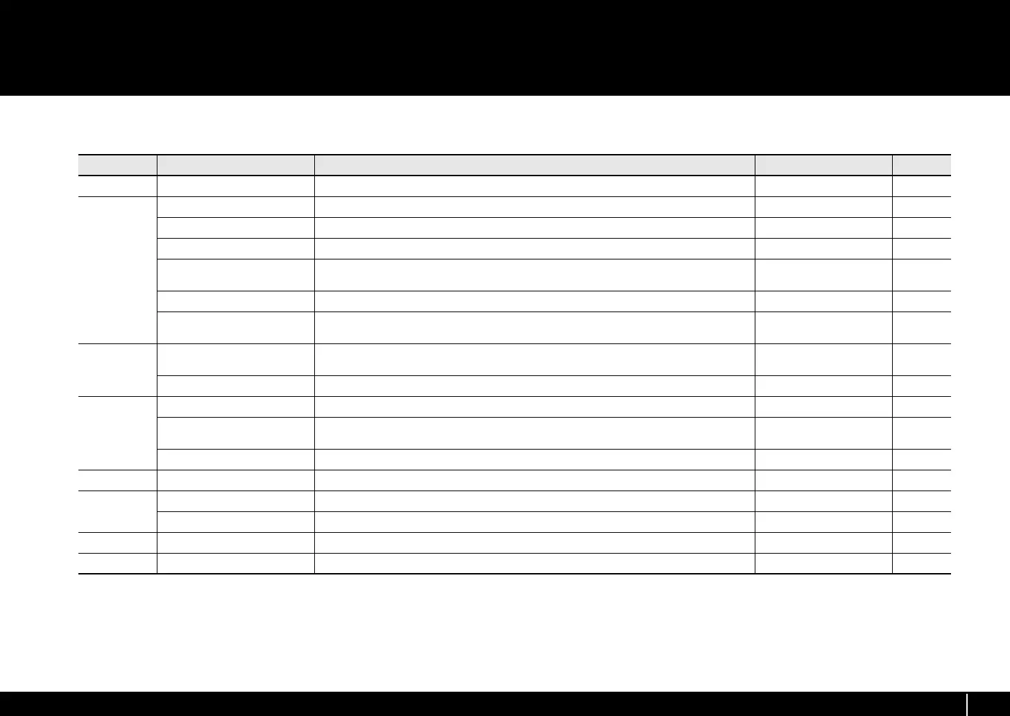
57
System Settings (EDIT Mode)
This section explains how to make system settings for the A-PRO.
System settings include the following items.
Category Item Contents Factory setting See page
LCD LCD CONTRAST Adjusts the LCD contrast. 5 p. 59
Keyboard
KEYBOARD VELOCITY CURVE Specifies how velocity will change in response to keyboard dynamics (velocity curve). 1-MEDIUM p. 60
KEYBOARD AFTERTOUCH CURVE Specifies how keyboard aftertouch will respond. 1 p. 61
KEYBOARD PORT SET Specifies the port from which the keyboard and bender lever will transmit performance data. PORT 1 p. 61
KEYBOARD ACTIVE PART
Specifies the part(s) that will be affected by the [VALUE] knob, BENDER, MODULATION, AFTERTOUCH,
HOLD, and EXPRESSION controllers.
UPPER p. 62
TRANSPOSE Specifies how the keyboard will be transposed when you turn on the [TRANSPOSE] button. 2 p. 62
SHIFT KEY LATCH
Specifies whether the [SHIFT] button will operate in Unlatched mode (turning on when pressed, turning off
when released) or in Latched mode (alternately turning on/off each time it is pressed).
UNLATCH p. 62
Pads
PAD VELOCITY CURVE
Specifies how the velocity value transmitted when you strike a pad controller [A1]–[A8] will correspond to
the force with which you strike (velocity curve).
1 p. 63
PAD AFTERTOUCH CURVE Specifies how the pad controllers [A1]–[A8] will respond to aftertouch. 1 p. 63
Clock
MIDI CLOCK ON/OFF Specifies whether MIDI CLOCK will be transmitted. OFF p. 64
MIDI CLOCK DEFAULT TEMPO
Specifies the initial MIDI CLOCK value when “MIDI CLOCK ON/OFF” is On. After the power is turned on, this
tempo will be output until you move the [VALUE] knob to which TEMPO is assigned.
120 p. 64
MIDI CLOCK OUTPUT PORT When “MIDI CLOCK ON/OFF” is On, this specifies the port from which MIDI CLOCK is transmitted. PORT 1 p. 64
USB ADVANCED DRIVER MODE Switches the driver mode. ON p. 65
MIDI
MIDI I/F SWITCH Specifies whether the MIDI connectors will be used as a MIDI interface. ON p. 66
MIDI MERGE DESTINATION Specifies the port that will be merged when the [MIDI MERGE] switch is On. PORT 1 p. 67
Control map STARTUP MEMORY Specifies which control map is to be called up when the power is turned on. CTL MAP 0 p. 68
Controller FUNCTION Specifies the parameter that will be transmitted by the [VALUE] knob. KEY VELOCITY p. 68
A-300_500_800C_e.book 57 ページ 2010年2月22日 月曜日 午後9時13分
 Loading...