39
MIDI Implementation
7 Rejection “RJC” (4FH)
This message is transmitted if you wish to forcibly end communication for some reason. This
message could be transmitted in the following cases.
5
If the size and address value indicated in a “data transmit/receive request” or “data request”
was inappropriate, or if the device is not in a state in which it can transmit or receive data
5
If the address or number of the data that was transmitted is inappropriate
5
If data transmission/reception was stopped by a panel operation, etc.
5
If a communication error occurred
This message can be transmitted at any time by either device, and the device that receives it must
immediately stop communication.
Byte Explanation
F0H Exclusive status
41H Roland ID
DEV Device-ID
14H Model-ID (D-50)
4FH Command-ID
7FH EOX (End Of Exclusive)
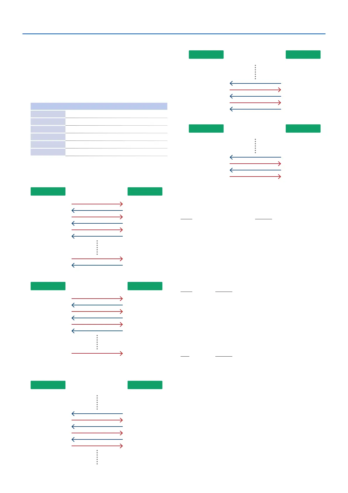
7 Example of the transmitting device
When device (A) transfers data to device (B)
Device A Device B
“Data set”
“Want to send data”
“Acknowiedge”
“Acknowiedge”
“Acknowiedge”
“Acknowiedge”
“Data set”
“End of data”
When device (A) requests data transmission from device (B)
Device A Device B
“Acknowiedge”
“Request data”
“Data set”
“Data set”
“End of data”
“Acknowiedge”
“Acknowiedge”
When an error occurs while device (A) is receiving data from device
(B)
1. When requesting retransmission of data from device (B)
Device A Device B
“Acknowiedge”
“Acknowiedge”
“Data set”
“Data set”
“Data set”
(same as above)
“Communication error”
(error occurs) x
2. When device (B) rejects data retransmission, and terminate communication
Device A Device B
“Acknowiedge”
(terminate)
“Data set”
“Data set”
“Rejection”
“Communication error”
(error occurs) x
3. When device (A) terminates immediately
Device A Device B
“Acknowiedge”
“Data set”
“Data set”
(terminate)
“Rejection”
(error occurs) x
9
3.5 Address mapping
7 Temporary area
Address Description
[00-00-00] Upper Partial-1 temp-area
[00-00-40] Upper Partial-2 temp-area
[00-01-00] Upper Common temp-area
[00-01-40] Lower Partial-1 temp-area
[00-02-00] Lower Partial-2 temp-area
[00-02-40] Lower Common temp-area
[00-03-00] Patch temp-area
7 Work area
The data in the bank of the currently selected patch can be transmitted and received using the
following addresses.
Address Description
[02-00-00] Patch Memory 1-1
[02-03-40] Patch Memory 1-2
: :
[03-5C-40] Patch Memory 8-8
[03-60-00] Reverb Data 17
[03-62-78] Reverb Data 18
: :
[04-0C-08] Reverb Data 32
Each patch memory has the following structure.
Oset Description
[00-00-00] Upper Partial-1
[00-00-40] Upper Partial-2
[00-01-00] Upper Common
[00-01-40] Lower Partial-1
[00-02-00] Lower Partial-2
[00-02-40] Lower Common
[00-03-00] Patch
 Loading...