15
Names of Things and What They Do
fig.right-side-panel.eps
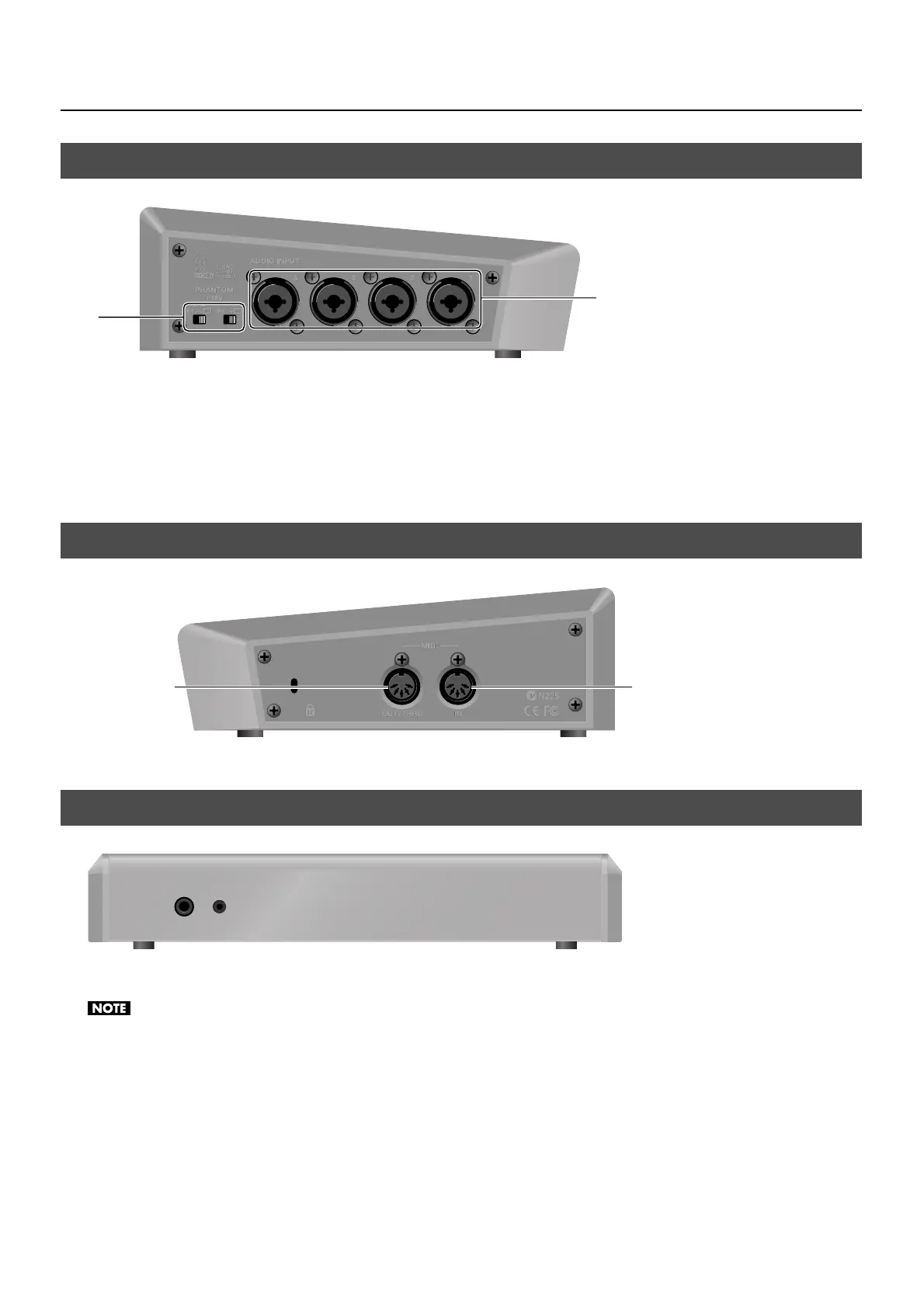
1. PHANTOM +48V Switch (p. 19)
This switches the phantom power of the AUDIO INPUT (XLR/TRS) connectors on and off. The unit has a switch for channels 1/2
and a switch for channels 3/4.
2. AUDIO INPUT (XLR/TRS) Connectors
These are for connecting microphones or an external audio mixer, or other audio sources. Input made via these connectors is
assigned to channels 1 through 4.
fig.left-side-panel.eps
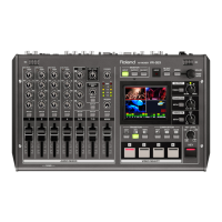
MIDI IN and MIDI OUT/THRU connectors are equipped here. You can connect external MIDI devices to remote control the VR-3.
Refer to “About Remote Control” (p. 48).
fig.front-panel.eps
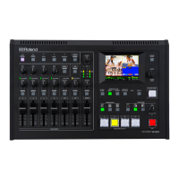
Two headphones (PHONES) connectors are located here. You can use these to connect standard-type (1/4-inch) headphones and
mini-stereo headphones.
The volume levels for the two PHONES connectors cannot be adjusted independently. Operating the [PHONES] dial changes the volume for both
simultaneously.
Left Side Panel
Right Side Panel
Front Panel
1
2
IN
OUT/THRU