Installation
EVBM-V01-R1 Installation and Operation Manual BasicCharge Intelligent EV Charging Pedestal
December 2022 Page 22 of 36
CAUTION; Equipment Damage – Sensitive Equipment
If you will be performing insulation resistance tests on the power supply cables, it is
advised to be done BEFORE connecting the cable to the chargepoint. The high
voltages applied during the test may damage sensitive components if tested after
the cable is connected.
IMPORTANT: If load balancing is required, install it alongside the next steps, before
completing the standard installation.
8. If required, install the optional Load Balancing system. Refer to page 23 Install Load
Balancing shown immediately after these ‘standard’ installation instructions.
9. When Load Balancing has been installed, return to this point.
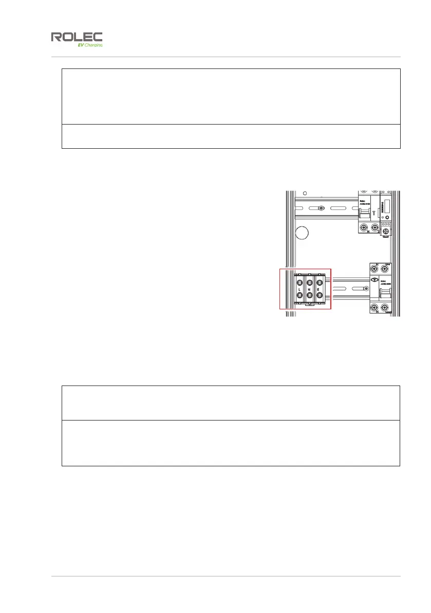
10. Route the incoming cables through the pedestal,
ready to connect to the appropriate terminals
within the enclosure.
11. Terminate the supply cable in the appropriate
manner and connect it to the pedestal.
12. If required, connect the Ethernet cable to the Smart Communications Module.
13. Make sure ALL debris is removed from the front and rear halves of the enclosure
and that no debris is present on any of the components.
NOTE: Debris and similar pollutants can adversely affect the performance and
working life expectancy of components and will invalidate the product/component
warranty.
IMPORTANT:
It is the responsibility of the installation engineer to satisfy themselves, that all
accessible cable terminations throughout this product are secure and have not
become loose, strained, or disconnected during transit and/or installation.
14. Make sure all cable connections are secure and have not become loose or
damaged in transit or during installation.
15. Switch ON the power to the chargepoint and test in accordance with the current
legislation applicable in the geographical region of the installation.
16. Make sure you are satisfied that the electrical installation is complete then, If
required, temporarily close the chargepoint enclosure for safety and security.
Access to the components will be needed during the configuration process.
Figure 14 Incoming Mains Power
Terminals (Single Phase Shown)