Installation
BasicCharge Intelligent EV Charging Pedestal EVBM-V01-R1 Installation and Operation Manual
Page 23 of 36 December 2022
Install Load Balancing
NOTE: This manual assumes the installation of a single chargepoint. Whilst multiple
chargepoints can be connected in a similar way, installers may wish to consider
connecting/monitoring via third-party equipment.
If connecting/monitoring via third-party equipment, make sure you are fully aware of
the manufacturer’s instructions so that the device/system can be installed correctly and
in conjunction with the chargepoint installation.
If load balancing will be enabled on this chargepoint it should, ideally, be installed
alongside the ‘standard installation’.
If installing at a later date, work may be required to enable entry of the CT cable into the
pedestal enclosure.
Overview
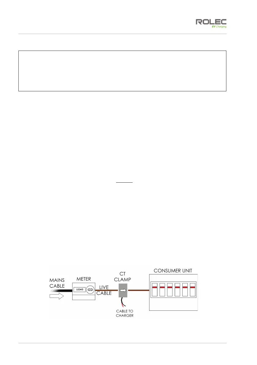
Power coming into the property is monitored by a Current Transformer (CT) that clamps
around the property’s incoming power cable and is then connected to the chargepoint.
x The CT has a cable allowing it to be connected to the chargepoint.
x Additional cable may be added to the CT cable but to maintain a good signal, it is
recommended that cables extensions are kept as short as possible.
Connect the CT to the Property
1. The CT clamp should be positioned around the Live (positive) cable between the
Meter and the Consumer Unit.
2. The arrow shown on the CT clamp must point in the direction of electrical flow
TOWARD the consumer unit.
x Alternatively, if required, the CT clamp may be positioned on the Negative
cable leaving the Consumer Unit. The arrow on the CT clamp must point in the
direction of electrical flow AWAY from the consumer unit.
3. Release the clip on the CT clamp then open the clamp.
4. Place the CT clamp around the power cable.
x Make sure the arrow on the clamp points in the correct direction.
x No other cables should pass though the CT clamp.
5. Close the CT clamp and secure it with the clip.
Figure 15 CT Clamp Positioning