Page 18 RS-500/600 Series Doors Part No 4801-5154 Rev 01-2017
13 Installation of RS-500/600 Series Doors
13.1 Tools Required
3/8 in. (10 mm) Power screwdriver (portable)
3/16 in. (5 mm) Drill bit and power drill
3/8 x 1 in. Bolts and nuts (supplied)
Socket
Hammer
Tape measure
Carpenter's level
NOTE: Other Tools May Be Required According To Installation.
13.2 Overview
The RS-500/600 Series doors are shipped with pre-assembled vertical members (left track and right track), and a
pre-assembled horizontal member (head unit). When components are received, check for damaged, loose or missing
parts. If there are damaged or missing parts contact your RollSeal distributor immediately. Please read and
understand all instructions in this manual before beginning installation.
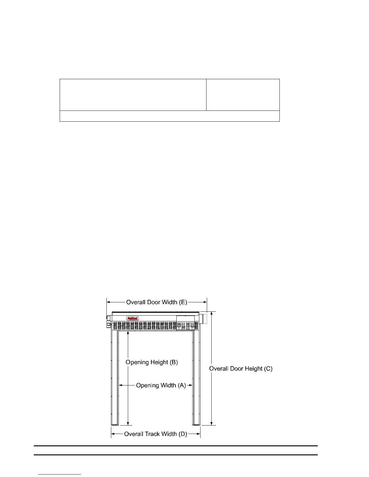
13.3 Adjusting the Door Framing or Clear Opening
Locate your particular system in the appropriate Tables 1-4 (Sections 9, 10, 11, and 12). Read the value of height
and width of the clear opening for the door size that you are installing. This gives the required dimensions of the
clear opening. If necessary, adjust the dimensions of the mounting posts or framing members to the height and
width of your RS-500/600 series door system as shown. Refer to Section 13.4, Page 19, Diagram 13A for details
of attaching door to framing members. Framing material must provide suitable support for attachment of screws.
Make sure that mounting posts or framing members are positioned so that the screw holes of the outer flanges of the
vertical members will align with the mounting posts or framing members (Section 13.4, Page 19, Diagram 13A).
NOTE: Make sure that there is space for appropriate motor, control box or Condensation Management
System (CMS) and freezer tracks (Freezer door option only) without encountering any
obstructions during installation. Refer to appropriate cut sheet (Sections 9, 10, 11, and 12), and
view the appropriate drawing of the door and operator to ensure required footprint.
NOTE: Allow 1' (30.4 cm) minimum, preferably 18" (45.7 cm) clearance above the Head Unit for future
panel maintenance or replacement.
 Loading...
