Quick Installation Guide
00825-0400-4101, Rev AA
March 2011
Rosemount 2051
12
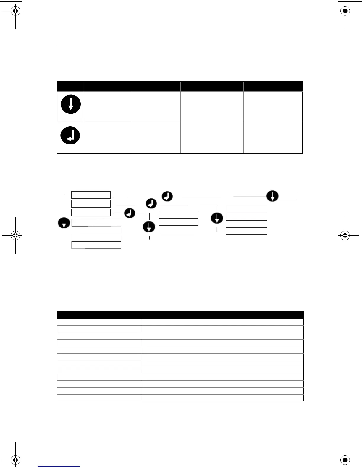
Table 1. LOI Button Operation
Figure 8. LOI Menu
Class 2 Master
The Rosemount 2051 PROFIBUS DD and DTM files are available at
www.EmersonProcess.com/Rosemount or by contacting your local salesperson. See
Table 2 for steps to configure the transmitter for Pressure measurement. See product
manual (00809-0300-4101) for Flow or Level configuration instructions.
Table 2. Pressure Configuration via Class 2 Master
Button Action Navigation Character Entry Save?
Scroll Moves down menu
categories
Changes character
value
(1)
(1)
(1) Characters blink when they can be changed.
Changes between Save
and Cancel
Enter Selects menu
category
Enters character and
advances
Saves
Steps Actions
Set blocks to Out of Service Put Transducer Block into Out of Service mode
Put Analog Input Block into Out of Service mode
Select Measurement Type Set Primary Value type to Pressure
Select Units Set Engineering Units
- Primary and secondary units must match
Enter Scaling Set Scale In in Transducer Block to 0 - 100
Set Scale Out in Transducer Block to 0 - 100
Set PV Scale in Analog Input Block to 0 - 100
Set Out Scale in Analog Input Block to 0 - 100
Set linearization in Analog Input Block to none
Set blocks to Auto Put Transducer Block into Auto mode
Put Analog Input Block into Auto mode
1. ADDRESS
6. IDENTIFICATION #
7. EXIT
4. DAMPING
5. DISPLAY
3. UNITS
2. CALIBRATION
PRESSURE
FLOW
LEVEL
TEMPERATURE
0-126
ZERO
LOWER SENSOR
UPPER SENSOR
RESET FACTORY
00825-0400-4101.fm Page 12 Friday, March 25, 2011 1:34 PM