Quick Installation Guide
00825-0400-4101, Rev AA
March 2011
Rosemount 2051
9
STEP 4: CONNECT WIRING AND POWER UP
Use the following steps to wire the transmitter:
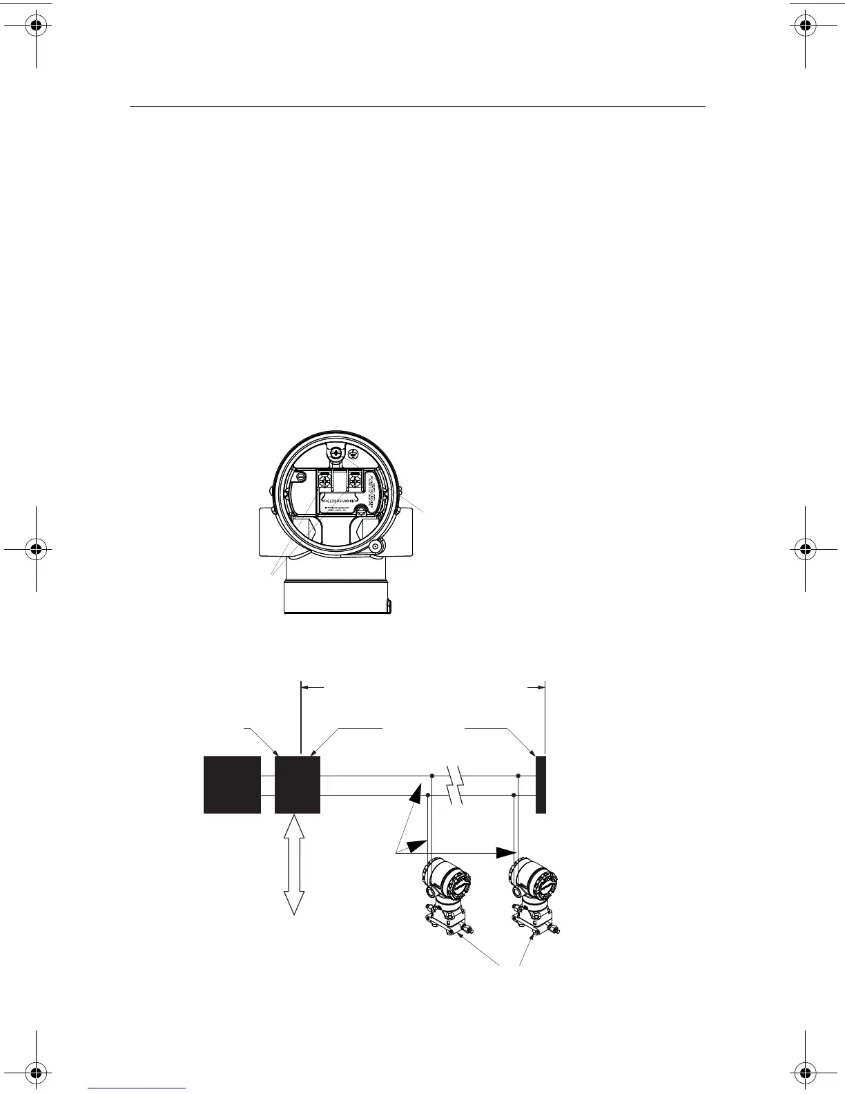
1. Remove the housing cover on the FIELD TERMINALS side.
2. Connect the power leads to the terminals indicated on the terminal block label.
• Power terminals are polarity insensitive - connect positive or negative to either terminal
3. Ensure proper grounding. It is important that the instrument cable shield:
• be trimmed close and insulated from touching the transmitter housing
• be connected to the next shield if cable is routed through a junction box
• be connected to a good earth ground at the power supply end
4. Plug and seal unused conduit connections.
5. If applicable, install wiring with a drip loop. Arrange the drip loop so the bottom is lower
than the conduit connections and the transmitter housing.
6. Replace the housing cover.
Figure 5.
Figure 6.
“NC” is a No Connect terminal (do not use)
Ground
Terminal
Power
Terminals
Power
Supply
DP/PA
Coupler
/Link
Terminators
6234 ft (1900 m) max
(depending upon cable
characteristics)
Integrated Power
Conditioner
and Filter
(Trunk)
(Spur)
(Spur)
Signal
Wiring
PROFIBUSPA Device
DP Network
00825-0400-4101.fm Page 9 Friday, March 25, 2011 1:34 PM