Reference Manual
00809-0100-4825, Rev BB
August 2005
2-7
Rosemount 248
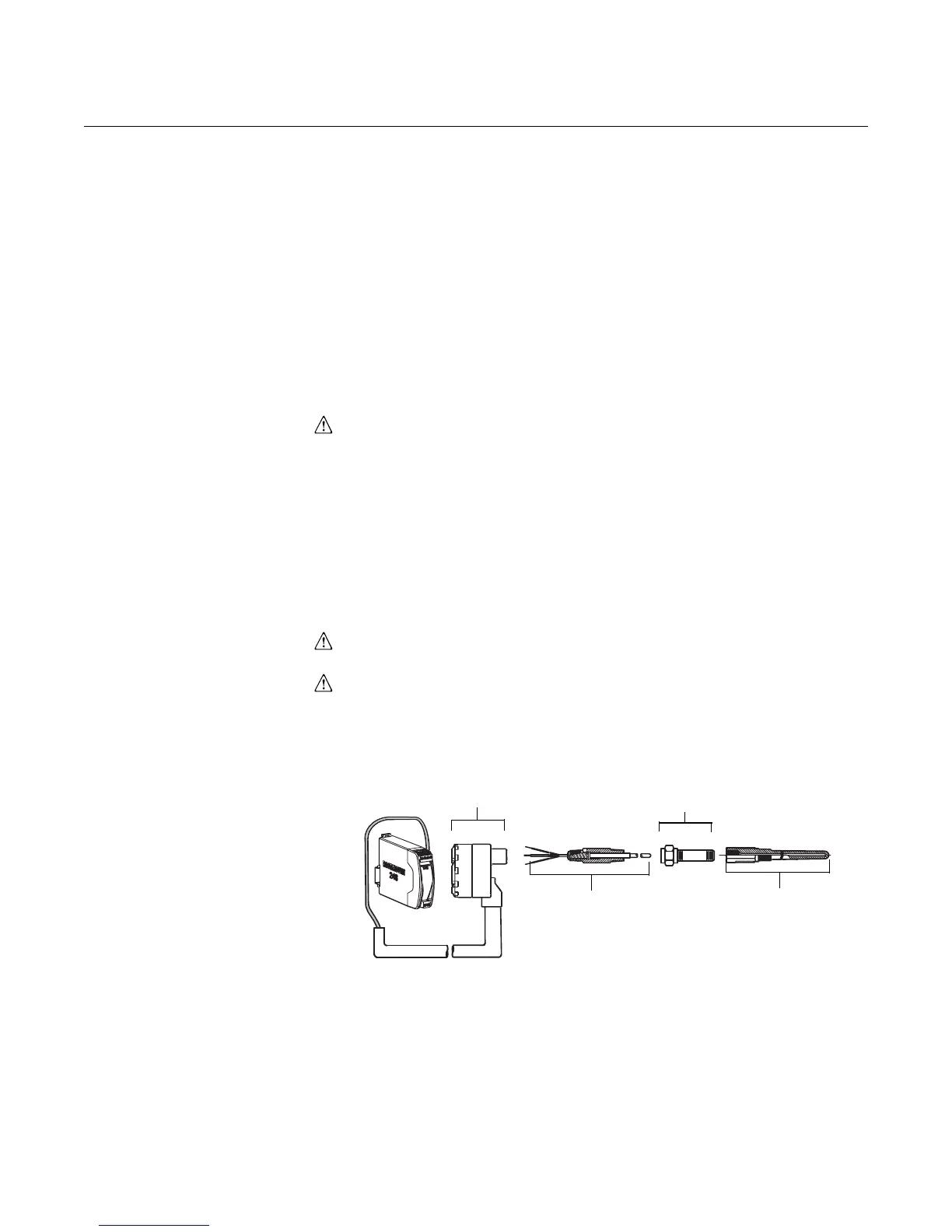
Rail Mount Transmitter with Threaded Sensor
The least complicated assembly uses:
• a threaded sensor with flying heads
• a threaded sensor connection head
• a union and nipple extension assembly
• a threaded thermowell
Refer to Volume 1 of the Rosemount Sensors Product Data Sheet (document
number 00813-0100-2654) for complete sensor and mounting accessory
information.
To complete the assembly, follow the procedure described below.
1. Attach the transmitter to a suitable rail or panel.
2. Attach the thermowell to the pipe or process container wall. Install
and tighten the thermowell before applying pressure.
3. Attach necessary extension nipples and adapters. Seal the nipple
and adapter threads with silicone tape.
4. Screw the sensor into the thermowell. Install drain seals if required for
severe environments or to satisfy code requirements.
5. Screw the connection head to the sensor.
6. Attach the sensor lead wires to the connection head terminals.
7. Attach additional sensor lead wires from the connection head to the
transmitter.
8. Attach and tighten the connection head cover. Enclosure covers must
be fully engaged to meet explosion-proof requirements.
9. Attach the sensor and power leads to the transmitter. Avoid contact
with leads and terminals.
Figure 2-4. Typical Rail Mount
Transmitter Mounting Configuration
Using Threaded Style Sensor
and Assembly
Rail Mount
Transmitter
Threaded
Style Sensor
Threaded
Thermowell
Standard
Extension
Threaded Sensor
Connection Head
248-0000A04B