Reference Manual
00809-0100-4825, Rev BB
August 2005
3-7
Rosemount 248
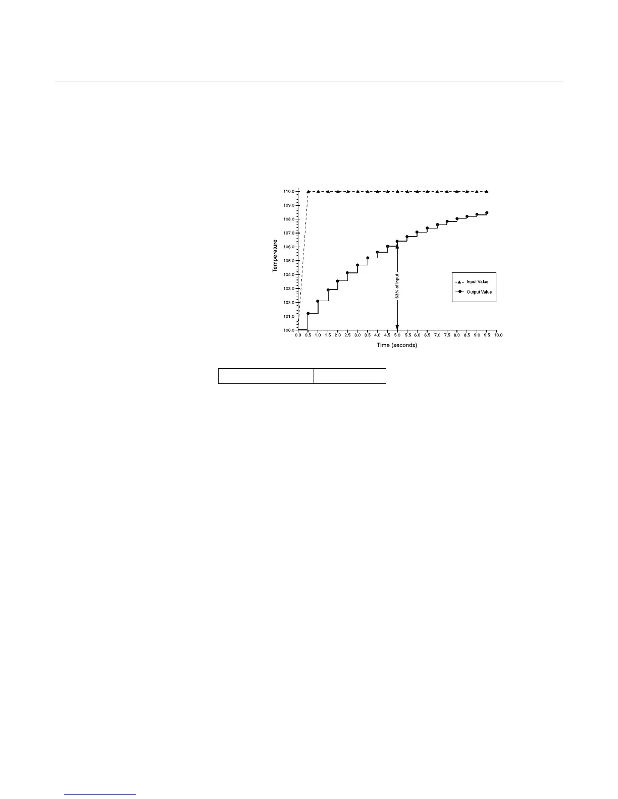
For example, as illustrated in Figure 3-1, if the temperature undergoes a step
change from 100 degrees to 110 degrees, and the damping is set to 5.0
seconds, the transmitter calculates and reports a new reading using the
damping equation. At 5.0 seconds, the transmitter outputs 106.3 degrees, or
63.2% of the input change, and the output continues to approach the input
curve according to the equation above.
Figure 3-1. Change in Input vs.
Change in Output with Damping
Set to Five Seconds
2-Wire RTD Offset
The 2-Wire RTD Offset command allows the user to input the measured lead
wire resistance, which will result in the transmitter adjusting its temperature
measurement to correct the error caused by this resistance. Due to a lack of
lead wire compensation within the RTD, temperature measurements made
with a 2-wire RTD are often inaccurate. See “Sensor Lead Wire
Resistance Effect– RTD Input” on page 2-10 for more information.
To utilize this feature perform the following steps:
1. Measure the lead wire resistance of both RTD leads after installing
the 2-wire RTD and the Rosemount 248.
2. From the HOME screen, select 1 Device Setup, 3 Configuration,
2 Sensor Configuration, 1 Sensor 1, 2 Snsr 1 Setup, and 1 2-Wire
Offset.
3. Enter the total measured resistance of the two RTD leads at the
2-Wire Offset prompt. Enter this resistance as a negative (–) value to
ensure proper adjustment.The transmitter then adjusts its
temperature measurement to correct the error caused by lead wire
resistance.
Fast Key Sequence 1, 3, 2, 1, 2, 1
644-644_01A