24
Reference Manual
00809-0100-4809, Rev DA
Section 2: Installation
September 2015
Installation
Step 3: Weld the mounting hardware
1. Center the Pak-Lok body over the mounting hole, gap
1
/16-in. (1.5 mm) and place four
1
/4-in. (6 mm) tack welds at 90° increments.
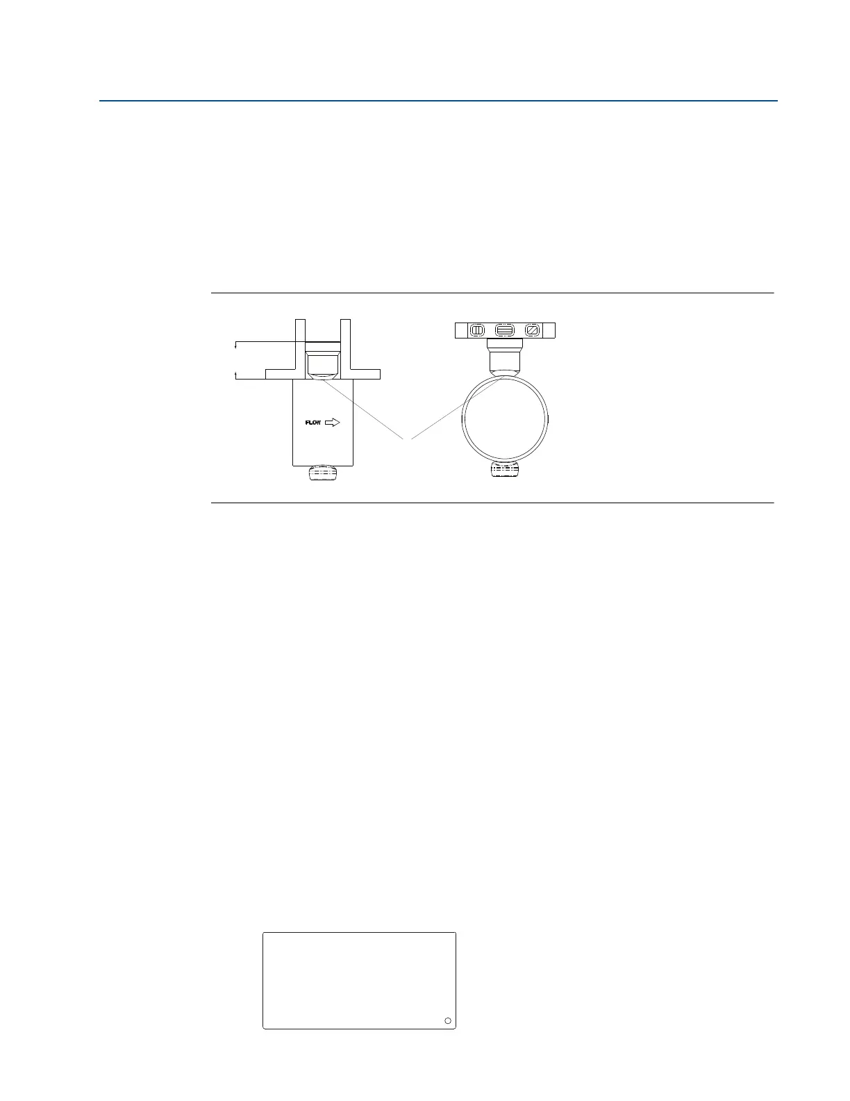
2. Check alignment of the Pak-Lok body both parallel and perpendicular to the axis of
flow. If alignment of mounting is within tolerances (see Figure 2-15), finish weld per
local codes. If alignment is outside of specified tolerance, make adjustments prior to
finish weld.
Figure 2-15. Alignment
A. Tack welds
3. If opposite side support is being used, center the fitting for the opposite side support
over the opposite side hole, gap
1
/16-in. (1.5 mm) and place four
1
/4-in. (6 mm) tack
welds at 90° increments. Insert the sensor into the mounting hardware. Verify that the
tip of the bar is centered in the opposite side fitting and verify that the plug will fit
around bar. If the bar is centered in the fitting and plug fits around the bar, finish weld
per local codes. If the alignment of the bar does not allow enough clearance to insert
the opposite side plug, make the necessary adjustments prior to making the finish
weld.
4. To avoid serious burns, allow the mounting hardware to cool before continuing.
Step 4: Insert Annubar sensor
After the mounting hardware has cooled, use the following steps for installation.
1. Thread studs into the Pak-Lok body.
2. To ensure the flowmeter contacts the opposite side wall, mark the tip of the sensor with
a marker. (Do not mark if the sensor was ordered with special-cleaned option code P2 or
PA.)
3. Insert the flowmeter into the Pak-lok body until the sensor tip contacts the pipe wall (or
support plug). Rotate the flowmeter back and forth.
4. Remove the flowmeter.
LMH
A
Serial No. Date
Model
Customer Tag
Pipe I.D. Wall
Max. Allow FlowRate
Max. Insert/Retract Flow
Max. Press. @ Temp
Span (20mA)
00-370000-2X1 Rev. AC