48 Configuration, Startup and Operation
Section 3: Configuration, Startup and Operation Reference Manual
January 2019 00809-0100-4892
The 375/475 Field Communicator accomplishes its task using a frequency shift keying (FSK)
technique. With the use of FSK, high-frequency digital communication signals are superim-
posed on the 6888Xi's 4-20 mA current loop. The 375/475 Field Communicator does not disturb
the 4-20 mA signal, since no net energy is added to the loop.
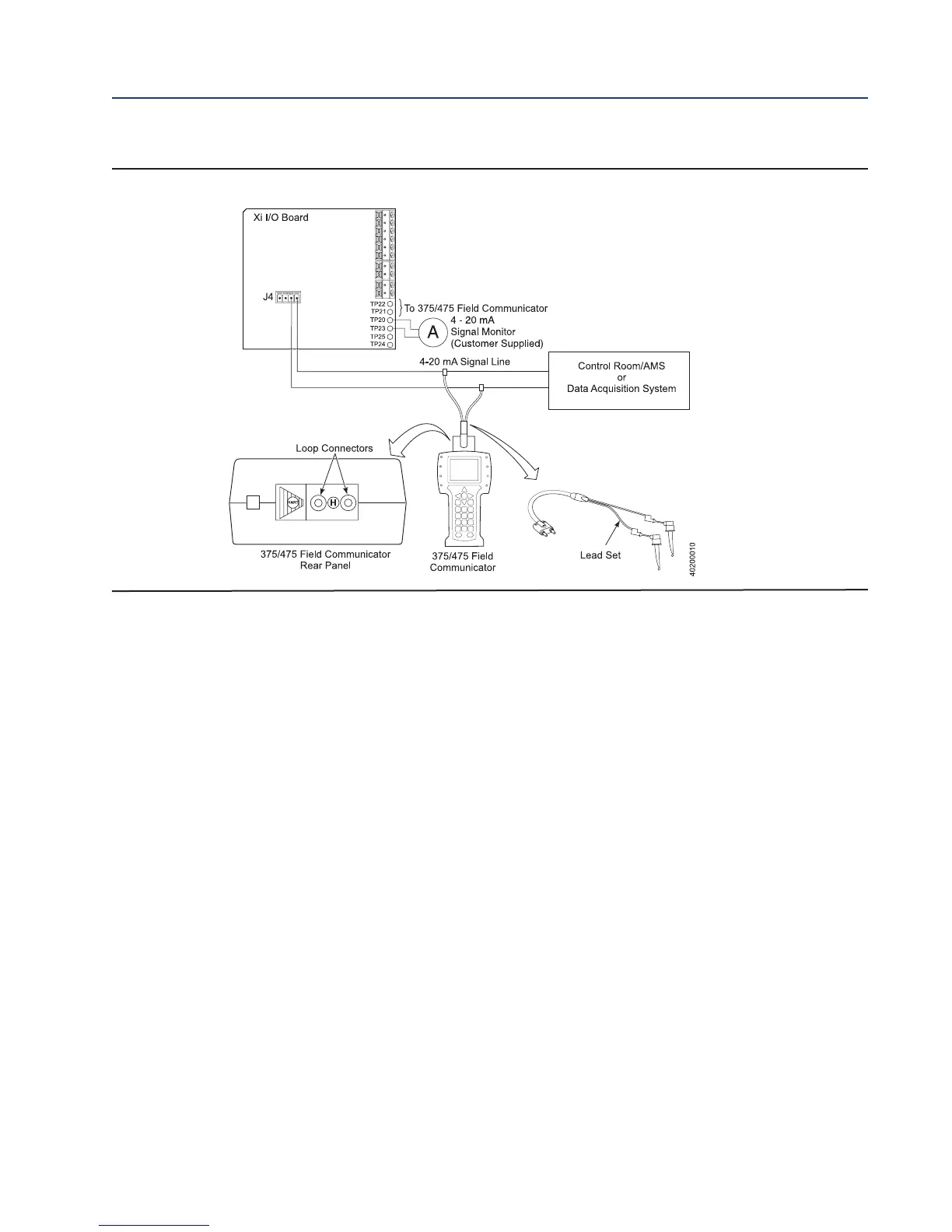
3.6.1 Field Communicator Signal Line Connections
When working at the 6888Xi, the 375/475 Field Communicator can be connected directly to
test points TP21 and TP22 on the 6888Xi I/O Board as shown in Figure 3-5. The AM+ and AM-
test points are provided to monitor the 4-20 mA signal without breaking into the loop.
3.6.2 Field Communicator Menu Trees
Connect the 375/475 Field Communicator in the 6888Xi (6888Xi-to-DCS) 4-20 mA signal loop
or to the 6888Xi terminals as shown in Figure 3-5 and refer to Figure 3-6 for the 375/475 Field
Communicator 6888Xi menu tree.
3.7 Parameter Setup
3.7.1 Test Gas Values
Use a Field Communicator or the 6888Xi to set test gas values for calibration.
FIGURE 3-5. 375/475 Field Communicator Connection at the 6888Xi