Reference Manual Section 5: Maintenance and Service
00809-0100-4892 January 2019
Maintenance and Service 87
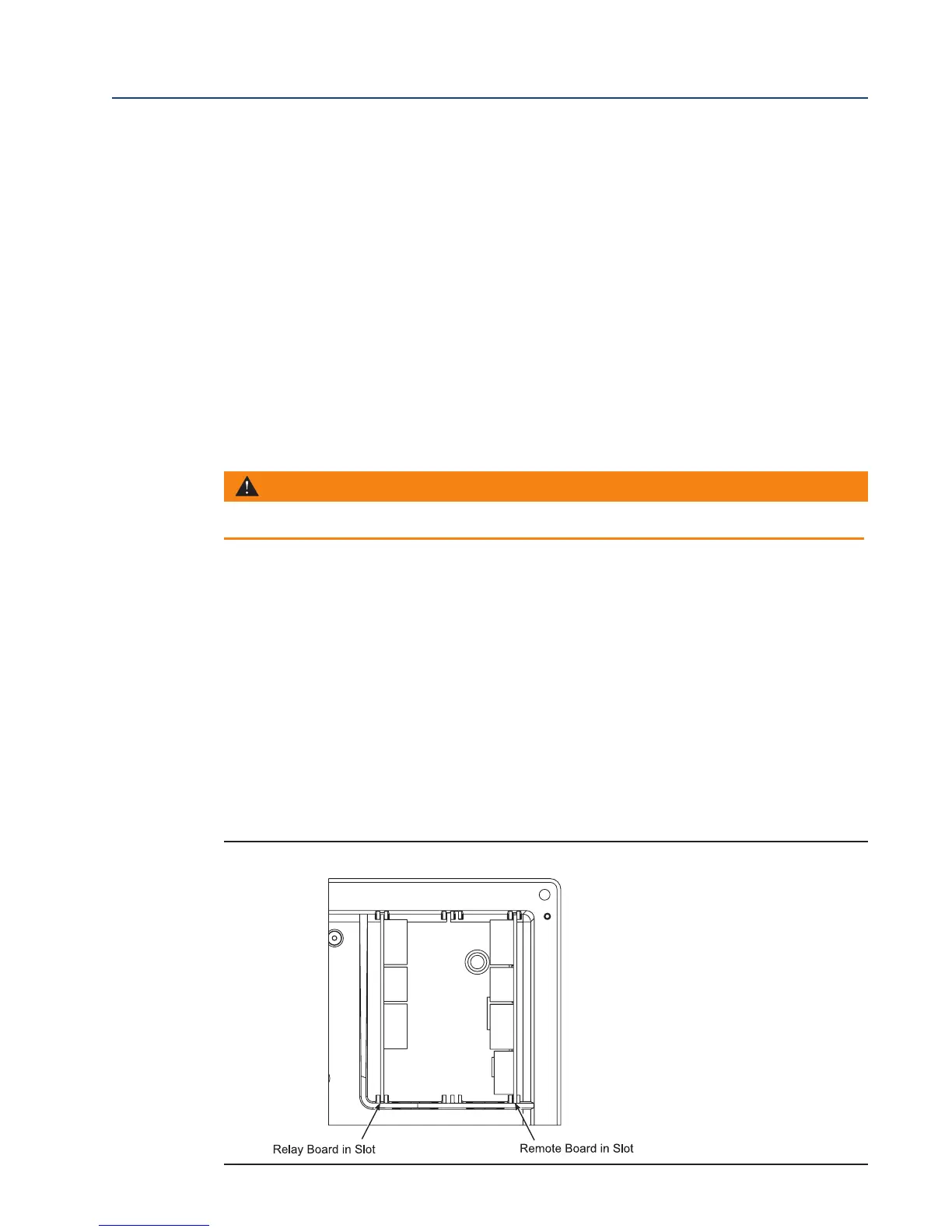
7. Partially slide the AC Relay Board into the left-most slot of the 6888Xi enclosure. The com-
p
onent side of the AC Relay board will be to the right with the fuse holder at the top. Ensure
the board is correctly aligned within the slots in the enclosure. See Figure 5-8 for the correct
location of the AC Relay Board.
8. Connect two wires approxmately 6" long each between the "HTR COM" and the "HTR NC"
connections on the I/O Board and the "RELAY IN"connections on the AC Relay Board;
observe polarity. See Figure 5-7 for wiring details.
9. Connect the flame status indicator contact to the "DI+" and "DI-" on the AC Relay Board. See
Figure 5-7 for wiring details.
10. Connect the AC input and output wiring to the Transmitter. See Figure 5-7 for wiring
details.
11. Slide the AC Relay Board completely into the 6888Xi enclosure.
12. Swing the cover up in place and tighten the four screws.
5.5.3 Power Supply Board Replacement
Use the procedure that follows to replace the Power Supply board in the 6888Xi. Use this proce-
dure to replace an original Linear Power Supply board or the current configuration Switching
Power Supply board.
1. Loosen the four screws securing the 6888Xi cover. The screws are captive and do not need
to be completely removed.
2. Swing the 6888Xi cover down to expose the inner components.
3. Refer to the wiring diagram in Figure 5-9. Unplug the AC input wiring plug from the Power
Supply board. A new plug is supplied in the replacement kit and should be used if the
6888Xi plug is damaged.
4. Disconnect the 14-pin ribbon cable from the Power Supply board.
5. Remove the two long screws that secure the bracket (9, Figure 5-1) to the 6888Xi enclosure.
WARNING
Disconnect and lock out power before working on any electrical components.
FIGURE 5-8. I/O and AC Relay Board Position in 6888Xi Enclosure