AC-425 Panel Setup
AC-425 Hardware Installation and User Manual 15
3.2 Inputs Wiring – Supervised Inputs
When wiring the AC-425 for supervised inputs, resistors should be placed on
the input switch and not on the terminal block.
For more details, refer to Chapter 4.
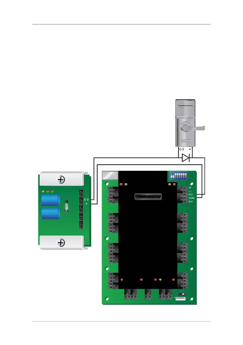
3.3 Outputs Wiring
Figure 4 and Figure 5 illustrate wiring for two main types of 12 VDC electrical
release mechanisms. Other electrical devices can be switched using the voltage
free relay contacts.
Figure 4: Door Lock – Failed Close
 Loading...