13
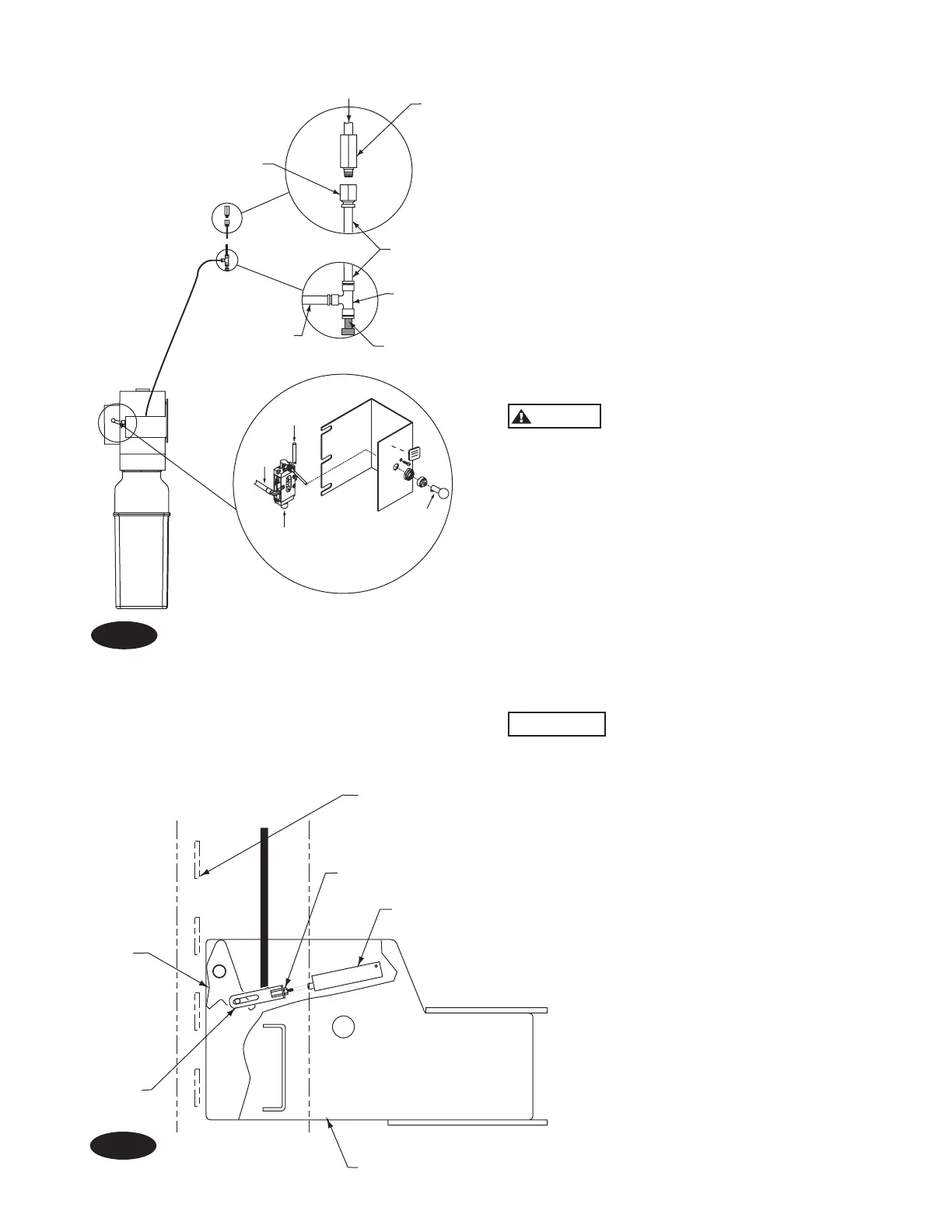
Latch
Jam Nut
Air Cylinder
Slotted
Bracket
13. Bleeding: Raise and lower lift (6) times. The cylinder is self-
bleeding. After bleeding system, replace fill vent screw.
Note: Some fluid may be exhausted from the cylinder breather
vent during bleeding of the system.
14. Pressure Test: To pressure test, run lift to full rise and run
motor for approximately five (5) seconds. Stop and check all hose
connections. Tighten or reseal if required. Lower lift. Check fluid
level in reservoir. Fill as required per instrustions in Step 11.
15. Final Adjustmemt:
A. Load vehicle, such as a 3/4 ton pickup or van onto lift.
B. Raise lift as high as it will travel (full height). As the lift is
raised, note in which rear column locking latch clicks into
slot at same time as the first column.
C. Adjust cable in other rear column so that its
locking latch clicks into slot at same time as the
first column.
There must be a minimum of two (2) threads
above the nut after adjustment.
D. Raise lift again. This time listening for the first front latch
to click into place. Adjust this simultaneously with the rear
columns.
E. Do the same for the remaining front column.
F. Tighten jam nuts and lower lift.
Note: Latches may not click in at the same time when vehicle is
being raised. They should be closed. Be sure all four (4) corners
have passed the locking latch bar slot before lowering lift on
locking latches.
Note: Replace any missing hardware with Grade 5 or higher.
Cotter pins are usually good for one time use
only. Replace any cotter pin, if removed, with new cotter pin.
16. Upon completion of the assembly of the lift, the lift is to
be operated to assure proper function. Observe for locks
operating in all locking positions, each side lifts equally,
hydraulics do not leak, all electrical controls function as
labeled, all pneumatics are functional and leak free, ramps
rotate freely (if applicable), and proper clearances with all
items in bay have been maintained.
Operate the lift with a typical vehicle and observe to assure
the same items for proper functioning.
Fig. 24
Fig. 25
3
/
8
” Air
Line
Connect Air Supply to Air Valve
Filter
Air Supply
Female
Connector
Reducing
Tee
Plastic
Plug
Air Valve
1
/
4
” Air Line
Air
Output
Air
Input
Push
Lever
 Loading...