APPENDIX A - Stop Bolt Adjustment
Page 10 of 12
1.2 Spring Canister
(See figure 2)
1.2.1 Remove the spring stop cap.
1.2.2 Depressurize the cylinder to
allow the spring to relax.
Failure to do so may result in
damage to the actuator!
1.2.3 Adjust the spring stop in/out as
desired.
1.2.4 Pressurize to outboard side of
power cylinder sufficiently to
induce a complete stroke of
the actuator and then check
the stop position.
1.2.5 Repeat steps 1.2.2 - 1.2.4 as
necessary to achieve desired
degree of travel.
1.2.6 Once the desired position is
achieved, replace spring stop
cap.
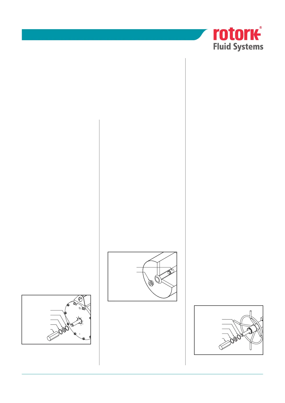
1.1 Pneumatic/Hydraulic
Cylinder (See figure 1)
1.1.1 Remove stop bolt cover.
1.1.2 Loosen stop nut.
1.1.3 Apply pressure to outboard
side of cylinder to remove load
from stop bolt. Failure to do so
may result in damage to the
actuator!
1.1.4 Adjust stop bolt in/out as
desired.
1.1.5 Remove pressure from cylinder
to verify stop position.
1.1.6 Repeat steps 1.1.3 - 1.1.5 as
necessary to achieve desired
degree of travel.
1.1.7 Once desired position is
achieved, tighten stop nut,
ensuring sealing washer is
properly centered on the shaft
and fitted in the machined
recess in the flange.
1.1.7 Re-install stop cover, ensuring
sealing washer is properly
centered on the shaft and
fitted in the machined recess in
the stop cover.
1.0 Overview
All RFS G Range actuators (ie., GP, GH, GO and HPG) incorporate adjustable stops
to limit the degree of travel in both directions. Steps are outlined below for
adjustment of the three stop configurations: pneumatic/hydraulic cylinder, spring
cartridge and, jackscrew.
Actuators may be damaged by improper adjustment procedure. Strictly follow
the instructions as outlined below with particular attention to the warnings is
steps 1.1.3, 1.2.2, 1.3 and 1.3.3.
1.3 Jackscrew
(See figure 3)
Note: The jackscrew is not designed
to function as a travel stop.
Stroking the actuator against
the jackscrew may damage it.
1.3.1 Remove stop bolt cover.
1.3.2 Loosen stop nut.
1.3.3 Turn jackscrew fully in to
compress spring and remove
any load from the stop. Failure
to do so may result in damage
to the actuator!
On fail close actuators, this is
d o n e b y t u r n i n g t h e
handwheel anti-clockwise.
On fail open actuators, this is
d o n e b y t u r n i n g t h e
handwheel clockwise.
1.3.4 Adjust stop bolt in/out as
desired.
1.3.5 Back jackscrew out (opposite
direction of as determined in
1.3.3) until seated against stop
screw to verify stop position.
1.3.6 Repeat steps 1.3.3 - 1.3.5 as
necessary to achieve desired
degree of travel.
1.3.7 Once desired position is
achieved, tighten stop nut,
ensuring sealing washer is
properly centered on the shaft
and fitted in the machined
recess.
1.3.8 Re-install stop cover, ensuring
sealing washer is properly
centered on the shaft and
fitted in the machined recess in
the stop cover.
figure 2
figure 1
figure 3
STOP SCREW
STOP NUT
SEALING WASHER
SEALING WASHER
STOP BOLT COVER
STOP SCREW
STOP NUT
SEALING WASHER
SEALING WASHER
STOP BOLT COVER
SPRING STOP
SPRING STOP CAP
INSTALLATION AND MAINTENANCE
GP RANGE
Publication F130E
Date of issue 04/08
 Loading...


