Do you have a question about the rotork IQ Series and is the answer not in the manual?
IQ actuators use multi-layered LCD screens for low temperatures, down to -50°C.
This manual guides users on installing, operating, and inspecting Rotork IQ actuators in low-temperature environments.
Identifies the Rotork Bluetooth® Setting Tool Pro (BTST) by key symbols and seals.
Illustrates and labels the navigation and configuration keys for the BTST tool.
Details the Bluetooth connection process, security, proximity requirements, and manual turn-off.
Actuator settings and values are shown on the segment portion of the LCD for current and setting values.
Example demonstrating the Torque Open setting (to) configured for 40% torque (40).
Visual flowchart illustrating the navigation path between different actuator settings.
Settings are viewable in Remote mode; editable in Local/Stop mode with password.
Procedure for entering the password and navigating between setting screens.
How to adjust values, save changes, or navigate without saving settings.
Defines Operating Direction (C1), Close Action (C2), and Open Action (C3) parameters.
Closing Torque (tC) adjustment range and increments.
Configuration of Opening Torque (tO), setting Close (LC) and Open (LO) limits.
Help screens indicate actuator status and aid diagnostics using segments.
Details display segments for Local Selector Input (H1) and Hardwired Input (H2).
Details display segments for Primary Control (H3) and Secondary Control (H4).
Details display segments for Alarm Status (H5) and Movement Status (H6).
Details display segments for Relay Status 1 (H7) and Relay Status 2 (H8).
Details display segments for Fault Status (H9) including Mains Fail and EEPROM.
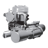
| Type | Electric Valve Actuator |
|---|---|
| Control | On/Off, Modulating |
| Power Supply | Single-phase, Three-phase |
| Torque Range | 14 Nm to 3, 000 Nm |
| Environmental Protection | IP68 |
| Network Communication | HART, Foundation Fieldbus, Modbus, Profibus |
| Data Logging | Yes |
| Diagnostic Capabilities | Yes |
| Display | LCD |
| Ambient Temperature Range | -30°C to +70°C |
| Certifications | ATEX, IECEx, CSA |
| Local Controls | Local control via selector switches and push buttons |