16
Master Station Safe Use, Installation and Maintenance Manual
5. Installation continued
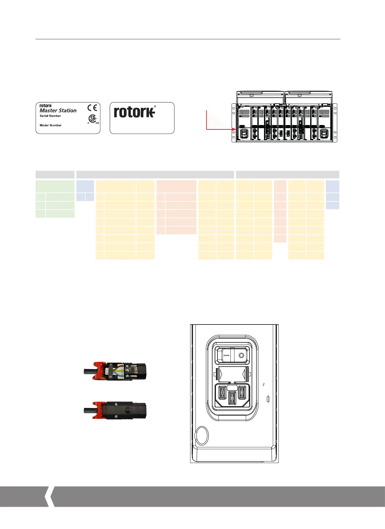
Nameplate
Every Master Station includes a nameplate detailing serial number and model number. The serial number uniquely identifies the Master
Station and can be used by the Rotork factory to trace the manufacturing details of the unit. This is a useful reference for upgrades
and spares enquiries. The model number defines the build configuration of the Master Station, whether it is hot standby, dual or single
configuration, the power supply rating, how many FCUs can be connected and which Add In Modules (AIMs) are fitted.
All dimensions in mm
Hot Standby Master Station, wall mounted
Side view with bracket in
wall mounting position
Single Master Station rack mounted
Side view with bracket in
19" rack mounting position
Bottom view
Hot Standby Master Station, wall mounted
Doors open
Hot Standby Master Station, rack mounted
Side view with bracket in
19" rack mounting position
Doors open
482
465
133 22
177
440
232
6
232
137
177
177 58
177
482
465
440
440
236
177
236
30Allow
minimum space
for cabling
Mounting position for
protruding Master Station
7
11
11
145
37
30Allow
minimum space
for cabling
88
7
45
Mounting position for
protruding Master Station
Location of
Nameplate
311B2BB1B2BB1
Z3660866770
Brassmill Lane, Bath, England
www.rotork.com
The red text below indicates the decoding of the model number 311B2BB1B2BB1: a Master Station with hot standby, AC PSU, Pakscan
Classic field network, 120 channels (FCUs).
Enclosure Left Hand Side Right Hand Side
Rack PSU LH Option 1 LH
Option
2 LH
CPU LH
Option
3 LH
Option
4 LH
Option
1 RH
Option
2 RH
CPU
RH
Option
3 RH
Option
4 RH
PSU
RH
1 Single 1 AC 1 Classic Field 1 1 60 Channels 1 1 1 1 1 1 1 1
2 Dual 2 Future 2 2 120 Channels 2 2 2 2 2 2 2 B
3 Hot Standby 3 Future 3 3 180 Channels 3 3 3 3 3 3 3
4 Modbus Field 4 4 240 Channels 4 4 4 4 4 4 4
5 Future 5 5 Future 5 5 5 5 5 5 5
6 Future 6 6 6 6 6 B 6 6
7 Host Serial 7 7 7 7 7 7 7
B Blank B B B B B B B
Power Connector and Ratings Label
The power connector supplied with the Master Station is an IEC 60320 C13 type with a locking mechanism. The red latch must be
pulled when connecting or disconnecting the power connector from the Master Station. Power rating information is shown on every
PSU module next to the power connection. The example below shows information for an AC PSU module.
Lower view of AC PSU module (P4740)
50/60Hz
50 VA
P4740
100
–
240 V
2A T 250V
A4US
US
A4
US A4
US
A4


 To Next Page