- 6 -
E4L E4
H L H L
RC210 90 68 120 68
RC220-RC265 90 110 120 110
RC270-RC280,
RC88
100 160 130 160
RCG90-RCG100 155* 200* 185* 200*
Tabell 14pt bold
Bold på rubriker uppe, allt under ska vara regular.
Allt utom spalten med RC-förteckningar ska vara
centrerat i våg och lodrätt. RC-spalten ska vara
vänsterlagd.
Strl på texten varierar beroende på utrymme men
10pt är standard
www.rotork.com www.remotecontrol.se
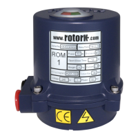
LIMIT SWITCH Setting
Close / Open Limit Cam Switch Setting
1. With the power off, remove the cover and manually rotate
the ACTUATOR to the closed, clockwise, position.
2. Loosen the close cam set screw and rotate the cam in a
clockwise direction to actuate the close limit switch. Also, the
close auxiliary switch camcan be adjusted at this time too.
AOLS Dry Open Limit Switch
ACLS Dry Close Limit Switch
OLS Open Limit Switch
CLS Close Limit Switch
3. Firmly tighten the cam set screws.
4. To set the open cam switches, repeat the previous instructions
except rotate the ACTUATOR to the open, counter-clockwise
position and rotate the open cams in the counter-clockwise
direction to actuate the open switches.
AOLS
OLS
ACLS
CLS
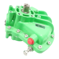
POTENTIOMETER Setting
• Actuator delivered full close at 80 ~ 120Ω
• After limit setting it should check at closed 80 ~ 120Ω
• Make actuator full closed and power off by moving of gear
• When nished setting the device, x the mudu bolt so that the gear will not move.
Warning when setting the POTENTIOMETER:
When setting the resistance value on the POTENTIOMETER, always
operate when the ACTUATOR power if OFF.
If the power is on, the resistance value on the calibrator will not show accurately.
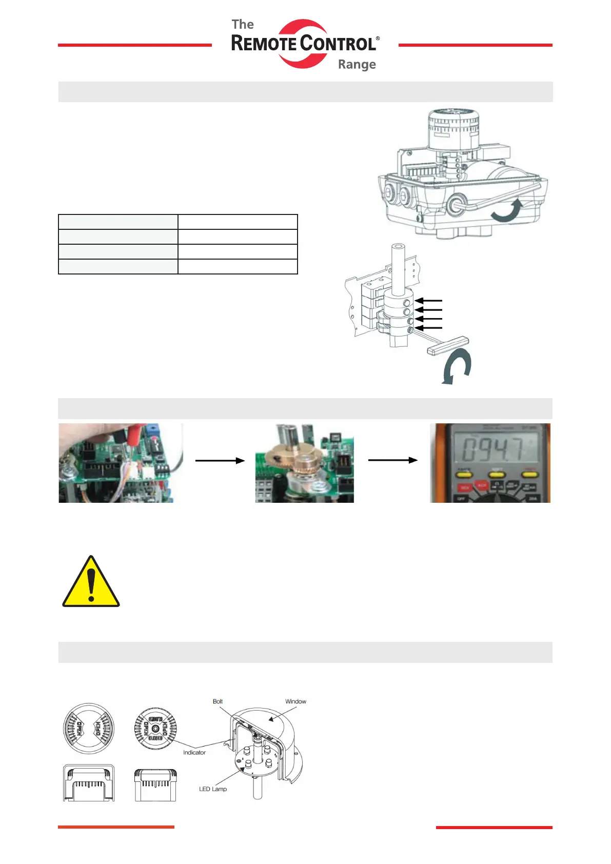
Indicator Setting
The position of the valve is indicated by the visual DOME
indicator.
LED lights illuminate to allow for easy visual conrmation
of valve position.
* If the position of the indicator is not aligned correctly,
an adjustment can be made by simply loosening the
bolt and manually turning the indicator to the proper
location, then re-tightening the bolt.
 Loading...